Defining Ethernet Physical Layer Terminology
Networking jargon can be context-sensitive, and many terms are often used interchangeably in conversation. In this article, I will define terms often used when discussing the physical layer of Ethernet networking. I will attempt to carefully balance the technical accuracy and precision of these definitions with how they are realistically used in everyday conversation between network operators.
Device
A device is a computer that transmits and receives information across a network. In most networks, there are two categories of devices:
- Hosts, which transmit and receive information between each other through the network. Hosts include desktop computers, laptops, phones, tablets, servers, and so on. Hosts are also sometimes called “end systems”, “end stations”, or simply “stations”.
- Network devices, which make up the network that hosts use to communicate with each other. Network devices relay information between hosts through the network. Network devices include switches, routers, firewalls, and so on.
Port
A port can refer to one of two things:
- A receptacle on a device where a transceiver is inserted. In this context, ports are sometimes colloquially called an “interface”, although there is a technical difference between a port and an interface.
- A receptacle or socket on a patch panel or coupler where a cable is inserted.
Transceiver
A transceiver is an electrical component that converts electrical signals from one form into another. Transceivers are inserted by operators into ports of a device and allow that port to connect to the network through a specific type of cable.
Below is an example of a transceiver that is not inserted in a device.
![]()
Below is an example of several transceivers inserted in a device.
![]()
Transceivers can have a variety of different form factors, which means they come in various shapes and sizes. A few examples include:
- GBIC (Gigabit Interface Converter)
- SFP (Small Form-Factor Pluggable)
- SFP+ (Enhanced Small Form-Factor Pluggable)
- QSFP (Quad Small Form-Factor Pluggable)
- XFP (X Form-Factor Pluggable, where “X” is the Roman numeral for “10”)
- CFP (C Form-Factor Pluggable, where “C” is the Roman numeral for “100)
Transceivers are sometimes referred to by their form factor in conversation (e.g. “Hey, can you hand me that QSFP?” or “We need to replace that SFP”). They are also sometimes called “optics” or MAUs (Medium Attachment Units, a term used in the IEEE 802.3 document that formalizes the Ethernet standard).
Some devices (particularly those that use twisted pair Ethernet cables) do not have transceivers. Instead, the twisted pair Ethernet cable connects directly to the device. An example of a switch (specifically, a Cisco Catalyst 3750) that is designed this way is shown below.
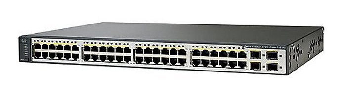
Note: Technically, these aforementioned devices do have transceivers, but they are built into the device. These are called MDIs (Medium-Dependent Interfaces) and are not removable by network operators. Threfore, for most troubleshooting and operational purposes, network operators should not consider these devices to have transceivers.
Cable
A cable is a physical medium that connects two transceivers or ports together. A cable is typically a bundle of either metal (normally copper) wires or optical fibers.
There are many different types and form factors of cables in the networking industry - too many to comprehensively list here! In my experience, the most common types observed in most modern networks are as follows:
- Copper cables
- Twisted pair cables
- Cat5
- Cat5e
- Cat6
- Cat6A
- Copper DACs (Direct Attach Cables)
- Active DACs
- Passive DACs
- Twisted pair cables
- Fiber optic cables
- Multi-mode
- OM1
- OM2
- OM3
- OM4
- OM5
- Single-mode
- OS1
- OS2
- Optical DACs (Direct Attach Cables)
- Multi-mode
The transceivers or ports that you need to connect together will determine the type of cable you need to use. For example, if you need to connect a transceiver that uses single-mode fiber cable to a single-mode fiber patch panel, then you must use a single-mode fiber cable.
Furthermore, for the most part, the same type of cable needs to be used throughout a link. For example, if you have two transceivers that use single-mode fiber cables, and you must connect both transceivers to each other through a pair of patch panels, the patch panels must support single-mode fiber; you should avoid using patch panels that only support multi-mode fiber (although in some scenarios, this specific example may work and result in a link coming up successfully and healthily).
In addition to having multiple different types and form factors, cables may also have many different connectors. Again, there are too many to comprehensively list here, but in my experience, here are some common connectors you will see in most modern networks:
- Copper cables
- 8P8C
- Fiber optic cables
- LC
- SC
- MTP/MPO
Link
A link is a series of one or more cables, patch panels, or couplers that connect two transceivers or ports to each other. In modern Ethernet networks, there are typically only two devices on an active Ethernet link. However, in early Ethernet networks, multiple devices could be connected to the same Ethernet link through 10BASE5 vampire taps to form a single Ethernet network segment or collision domain.
Patch Panel
A patch panel is a mounted piece of hardware that aggregates and organizes a large number of cables in a single physical location, allowing operators to easily connect devices to the network.
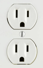
The value of a patch panel is best demonstrated through an example. Imagine an office suite consisting of multiple offices employees work in. Each employee will have one computer and one phone in their office, and both devices need to be connected to the network through twisted pair Ethernet cables. Similarly to how devices need power supplied by electrical wall outlets as shown below, both devices will need network connectivity through Ethernet wall outlets as shown below.

Electricians (or other certified tradespeople) will install twisted pair Ethernet cables between each office’s Ethernet wall outlet and a central location somewhere within the office suite (typically a facilities or telecommunications closet or room) through a dropped ceiling or crawlspace. One end of each cable will connect to the office’s Ethernet wall outlet, and the other end of the cable will be terminated in the back of a patch panel as shown below.
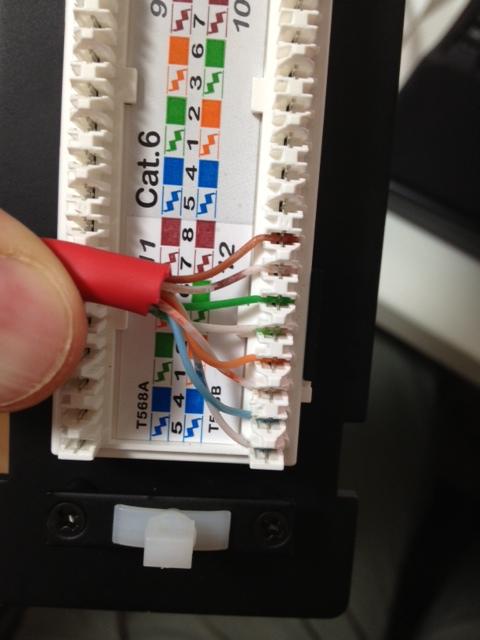
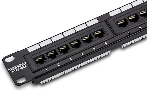
Since this example is using twisted pair Ethernet cables, the front of the patch panel will have an 8P8C port where twisted pair Ethernet cables can be plugged in. There will also be space for a label associated with each 8P8C port, allowing operators to indicate where the relevant cable connects to in the office (such as a specific jack in a room number).
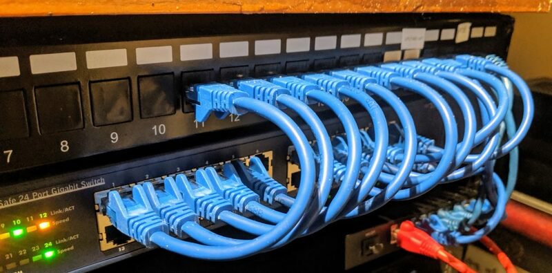
Each port will then typically connect to a port on a network switch as shown below.
To summarize this example, a patch panel is used to connect a host (e.g. a computer or phone) to a network device (a switch), as shown by the diagram below.

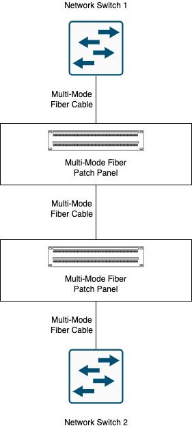
However, patch panels can also be used to connect two network devices together. This is common in data center or lab environments, where a network device in one row of the data center needs to be connected to a network device in a different row of the data center. Furthermore, patch panels are not limited to twisted pair Ethernet cables. Patch panels for fiber-optic cables exist and are in common use in data center environments that need 10Gbps or higher speeds. This type of use case is shown by the diagram below.
Coupler
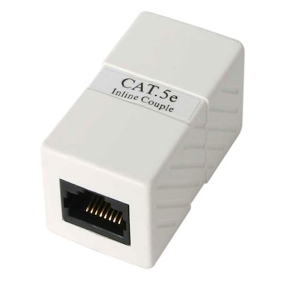
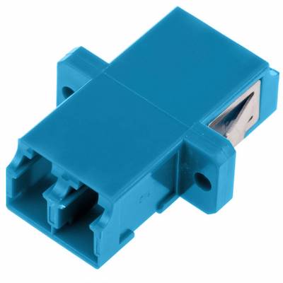
A coupler is a piece of hardware that connects two cables of the same type together. This is very similar in function to a patch panel except that a patch panel is typically mounted in a rack, while a coupler sits “in-line” between two cables.
Two examples of couplers are shown below - one for twisted pair Ethernet cables, and another for fiber optic cables with LC connectors.