TAC Tales - How IP SLA and Static Routes Ruined Christmas
It was Christmas Day of 2019, and I was working the holiday shift in Cisco TAC. Working Christmas is enjoyable - it tends to be quiet, and in the rare case you need to assist with an issue or outage, customers are nice and in good spirits.
On this day, a case came in requesting a Root Cause Analysis (RCA) for an outage that happened a few hours ago. The outage lasted about 23 minutes in length, and the environment recovered on its own. After meeting with the customer over Webex and reviewing the situation, I found a topology similar to the below, which I simulated in the lab using Cisco Modeling Labs with Cisco Catalyst 8000v virtual routers.

This topology has three routers - R1, R2, and R3. The customer reported the outage affected north-south traffic from Host to IPs behind the R3 router. In our lab, these IPs are simulated by R3’s Loopback0 interface assigned IP address 100.3.3.3/32. R1 and R2 are iBGP peers.
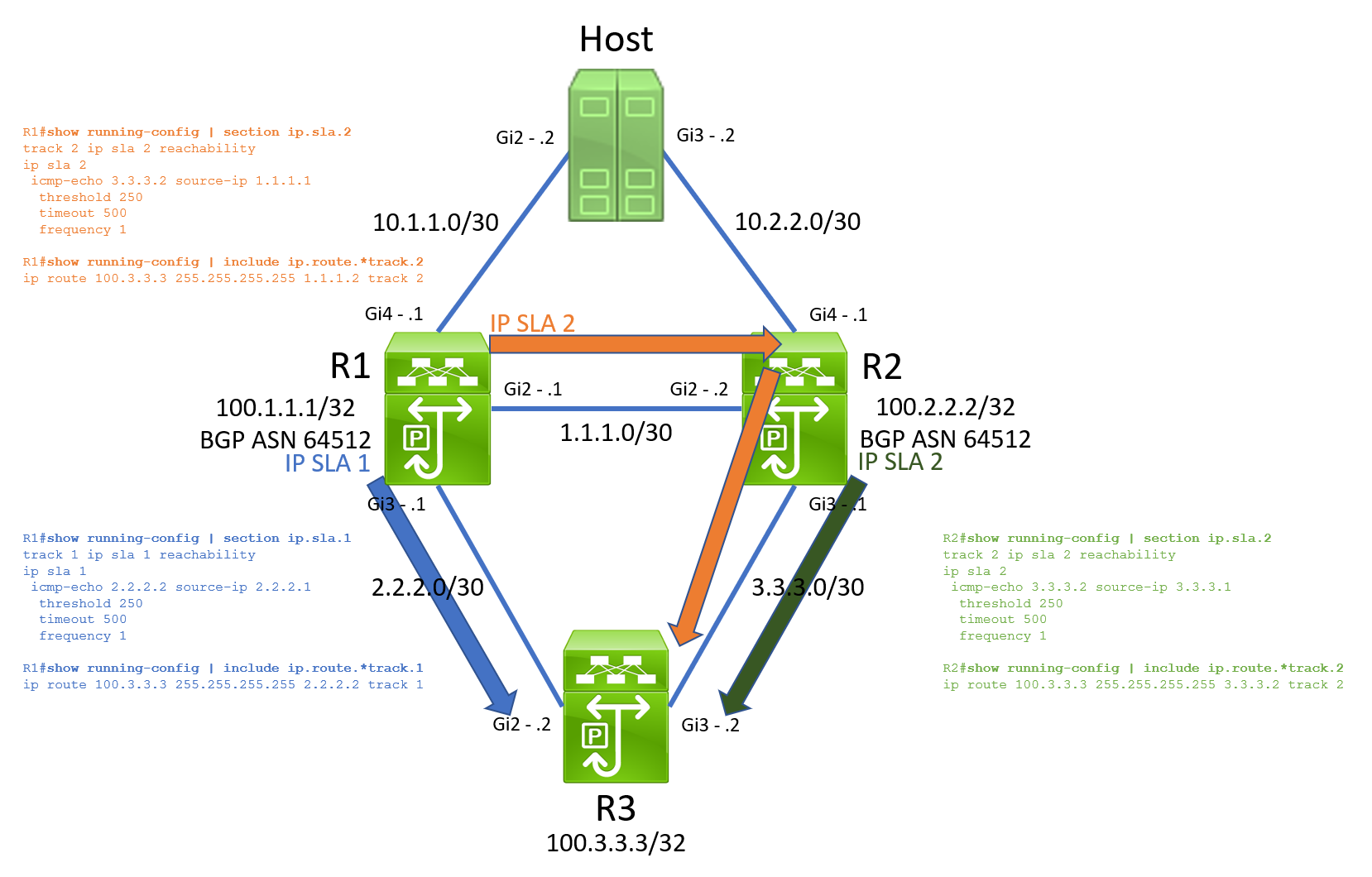
After reviewing each device’s configuration and how traffic is routed, I found this topology combined IP SLA operations, track objects, and static routes to establish southbound Layer 3 reachability. The table below shows how each IP SLA operation is configured.
| Source Router | IP SLA Operation ID | Source Interface | Source IP | Destination IP | Destination Interface | Destination Router |
|---|---|---|---|---|---|---|
| R1 | 1 | GigabitEthernet3 | 2.2.2.1 | 2.2.2.2 | GigabitEthernet2 | R3 |
| R1 | 2 | GigabitEthernet2 | 1.1.1.1 | 3.3.3.2 | GigabitEthernet3 | R3 |
| R2 | 2 | GigabitEthernet3 | 3.3.3.1 | 3.3.3.2 | GigabitEthernet3 | R3 |
| R3 | 1 | GigabitEthernet2 | 2.2.2.2 | 2.2.2.1 | GigabitEthernet2 | R1 |
| R3 | 2 | GigabitEthernet3 | 3.3.3.2 | 3.3.3.1 | GigabitEthernet3 | R2 |
Visually, this means our topology with IP SLA operations looks like the below. Note that R3’s IP SLA operations to both R1 and R2 are not pictured here.
By the time the TAC case was opened, the topology had recovered from the outage. In its current state, I could only see the desired working state. In this working state, R1 had ECMP (Equal Cost MultiPathing) for 100.3.3.3/32 through R2’s 1.1.1.2 and R3’s 2.2.2.2.
1
2
3
4
5
6
7
8
9
10
11
12
13
14
15
16
17
18
R1#show ip route track-table
 ip route 100.3.3.3 255.255.255.255 2.2.2.2 track 1 state is [up]
 ip route 100.3.3.3 255.255.255.255 1.1.1.2 track 2 state is [up]

R1#show ip route 100.3.3.3
Routing entry for 100.3.3.3/32
  Known via "static", distance 1, metric 0
  Advertised by bgp 64512
  Routing Descriptor Blocks:
  * 2.2.2.2
      Route metric is 0, traffic share count is 1
    1.1.1.2
      Route metric is 0, traffic share count is 1

R1#show ip cef 100.3.3.3
100.3.3.3/32
  nexthop 1.1.1.2 GigabitEthernet2
  nexthop 2.2.2.2 GigabitEthernet3
In the working state, R2 had a single route for 100.3.3.3/32 through R3’s 3.3.3.2.
1
2
3
4
5
6
7
8
9
10
11
12
13
14
R2#show ip route track-table
 ip route 100.3.3.3 255.255.255.255 3.3.3.2 track 2 state is [up]

R2#show ip route 100.3.3.3
Routing entry for 100.3.3.3/32
  Known via "static", distance 1, metric 0
  Advertised by bgp 64512
  Routing Descriptor Blocks:
  * 3.3.3.2
      Route metric is 0, traffic share count is 1

R2#show ip cef 100.3.3.3
100.3.3.3/32
  nexthop 3.3.3.2 GigabitEthernet3
Finally, R3 had two default static routes through both R1’s 2.2.2.1 and R2’s 3.3.3.1, with preference placed on R2 through the static route’s metric.
1
2
3
4
5
6
7
8
9
10
11
12
13
14
R3#show ip route track-table
 ip route 0.0.0.0 0.0.0.0 2.2.2.1 2 track 1 state is [up]
 ip route 0.0.0.0 0.0.0.0 3.3.3.1 track 2 state is [up]

R3#show ip route 0.0.0.0
Routing entry for 0.0.0.0/0, supernet
  Known via "static", distance 1, metric 0, candidate default path
  Routing Descriptor Blocks:
  * 3.3.3.1
      Route metric is 0, traffic share count is 1

R3#show ip cef 0.0.0.0/0
0.0.0.0/0
  nexthop 3.3.3.1 GigabitEthernet3
In this working state, Host is able to ping 100.3.3.3 without issue.
1
2
3
4
5
Host#ping 100.3.3.3
Type escape sequence to abort.
Sending 5, 100-byte ICMP Echos to 100.3.3.3, timeout is 2 seconds:
!!!!!
Success rate is 100 percent (5/5), round-trip min/avg/max = 2/2/4 ms
You may notice that R1’s ECMP for 100.3.3.3/32 is inefficient. Approximately half of the traffic traversing R1 for this prefix will hash to R3, while the rest egresses towards R2, then be forwarded to R3. 100.3.3.3/32 is injected into BGP, and R1 and R2 are advertising this prefix to each other.
Note: Interested in why approximately half of the traffic for this prefix would egress towards R1, instead of definitely half? Check out my Understanding Load Balancing on Network Devices blog post for more details!
1
2
3
4
5
6
7
8
9
10
11
12
13
14
15
16
17
18
19
20
21
22
23
24
25
R1#show ip bgp
BGP table version is 2, local router ID is 100.1.1.1
Status codes: s suppressed, d damped, h history, * valid, > best, i - internal,
              r RIB-failure, S Stale, m multipath, b backup-path, f RT-Filter,
              x best-external, a additional-path, c RIB-compressed,
              t secondary path, L long-lived-stale,
Origin codes: i - IGP, e - EGP, ? - incomplete
RPKI validation codes: V valid, I invalid, N Not found

     Network          Next Hop            Metric LocPrf Weight Path
 * i  100.3.3.3/32     3.3.3.2                  0    100      0 i
 *>                    2.2.2.2                  0         32768 i

R2#show ip bgp
BGP table version is 12, local router ID is 100.2.2.2
Status codes: s suppressed, d damped, h history, * valid, > best, i - internal,
              r RIB-failure, S Stale, m multipath, b backup-path, f RT-Filter,
              x best-external, a additional-path, c RIB-compressed,
              t secondary path, L long-lived-stale,
Origin codes: i - IGP, e - EGP, ? - incomplete
RPKI validation codes: V valid, I invalid, N Not found

     Network          Next Hop            Metric LocPrf Weight Path
 *>   100.3.3.3/32     3.3.3.2                  0         32768 i
 * i                   2.2.2.2                  0    100      0 i
R1’s static route towards R2 is unnecessary, as the iBGP peering with R2 ensures an iBGP prefix will be installed in R1’s routing table if the static route for 100.3.3.3/32 is removed by the track object going down. This is part of the reason why Christmas was ruined!
Log Analysis
Since the issue was not presently happening, I collected logs from relevant devices for analysis. I found that just before the start of the outage, R2’s track object 2 transitioned from Up to Down because R2’s IP SLA 2’s reachability to R3 went down.
1
2
3
R2#show logging
<snip>
Mar 20 2022 22:38:31.719: %TRACK-6-STATE: 2 ip sla 2 reachability Up -> Down
Shortly afterwards, R1’s track object 2 transitioned from Up to Down because R1’s IP SLA 2’s reachability to R3 went down.
1
2
3
R1#show logging
<snip>
Mar 20 2022 22:38:32.571: %TRACK-6-STATE: 2 ip sla 2 reachability Up -> Down
Shortly afterwards, R3’s track object 2 towards R2 went down.
1
2
3
R3#show logging
<snip>
Mar 20 2022 22:38:32.790: %TRACK-6-STATE: 2 ip sla 2 reachability Up -> Down
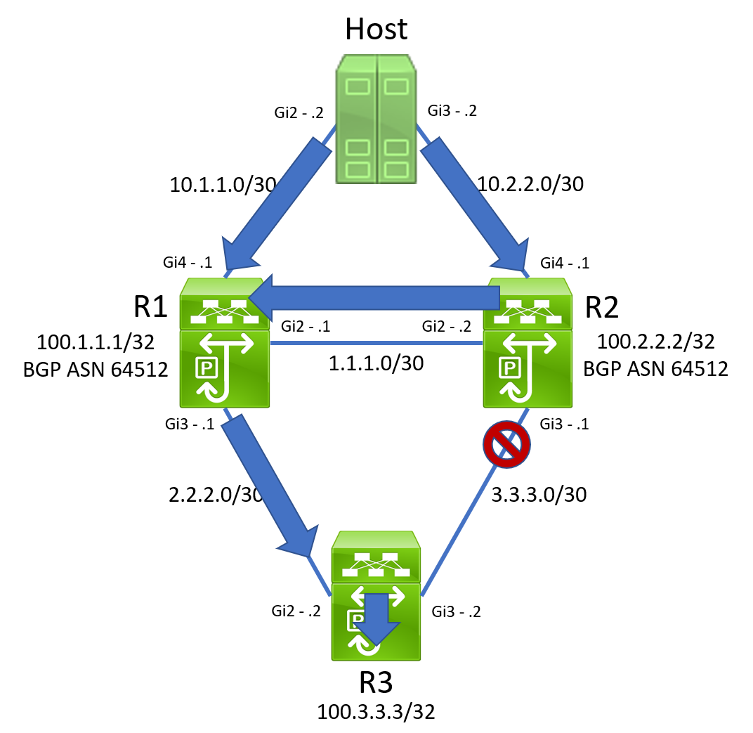
At this point, everything has converged as we expected. R3’s routing table has a default static route facing R1.
1
2
3
4
5
6
7
8
9
10
R3#show ip route 0.0.0.0
Routing entry for 0.0.0.0/0, supernet
  Known via "static", distance 2, metric 0, candidate default path
  Routing Descriptor Blocks:
  * 2.2.2.1
      Route metric is 0, traffic share count is 1

R3#show ip cef 0.0.0.0/0
0.0.0.0/0
  nexthop 2.2.2.1 GigabitEthernet2
R1 has a static route to 100.3.3.3/32 in its routing table towards R3.
1
2
3
4
5
6
7
8
9
10
11
R1#show ip route 100.3.3.3
Routing entry for 100.3.3.3/32
  Known via "static", distance 1, metric 0
  Advertised by bgp 64512
  Routing Descriptor Blocks:
  * 2.2.2.2
      Route metric is 0, traffic share count is 1

R1#show ip cef 100.3.3.3/32
100.3.3.3/32
  nexthop 2.2.2.2 GigabitEthernet3
Finally, R2 has a BGP-learned route to 100.3.3.3/32 in its routing table towards R1.
1
2
3
4
5
6
7
8
9
10
11
12
13
14
R2#show ip route 100.3.3.3
Routing entry for 100.3.3.3/32
  Known via "bgp 64512", distance 200, metric 0, type internal
  Last update from 2.2.2.2 00:10:12 ago
  Routing Descriptor Blocks:
  * 2.2.2.2, from 100.1.1.1, 00:10:12 ago
      opaque_ptr 0x7F844DD08130
      Route metric is 0, traffic share count is 1
      AS Hops 0
      MPLS label: none

R2#show ip cef 100.3.3.3
100.3.3.3/32
  nexthop 1.1.1.1 GigabitEthernet2
Although we’re not yet sure why the reachability of IP SLA 2 on R2 went down, all is well with the world, and Christmas is not yet ruined. All reachability to 100.3.3.3/32 must go through R1, which pushes traffic down to R3.
Suddenly, R1’s track object 2 transitioned from Down to Up because R1’s IP SLA 2’s reachability to R3 comes back.
1
2
3
R1#show logging
<snip>
Mar 20 2022 22:38:37.572: %TRACK-6-STATE: 2 ip sla 2 reachability Down -> Up
The 100.3.3.3/32 static route through R2 is then reinserted into the routing table.
1
2
3
4
5
6
7
8
9
10
11
12
13
14
R1#show ip route 100.3.3.3
Routing entry for 100.3.3.3/32
  Known via "static", distance 1, metric 0
  Advertised by bgp 64512
  Routing Descriptor Blocks:
  * 2.2.2.2
      Route metric is 0, traffic share count is 1
    1.1.1.2
      Route metric is 0, traffic share count is 1

R1#show ip cef 100.3.3.3/32
100.3.3.3/32
  nexthop 1.1.1.2 GigabitEthernet2
  nexthop 2.2.2.2 GigabitEthernet3
However, R2’s routing table has not changed. Its reachability to 100.3.3.3/32 still points back towards R1.
1
2
3
4
5
6
7
8
9
10
11
12
13
14
R2#show ip route 100.3.3.3
Routing entry for 100.3.3.3/32
  Known via "bgp 64512", distance 200, metric 0, type internal
  Last update from 2.2.2.2 00:10:12 ago
  Routing Descriptor Blocks:
  * 2.2.2.2, from 100.1.1.1, 00:10:12 ago
      opaque_ptr 0x7F844DD08130
      Route metric is 0, traffic share count is 1
      AS Hops 0
      MPLS label: none

R2#show ip cef 100.3.3.3
100.3.3.3/32
  nexthop 1.1.1.1 GigabitEthernet2
When a packet destined to 100.3.3.3/32 traverses R1 and hashes towards R2, R2 will reflect that same packet back at R1. Due to the way hashing algorithms are implemented, when that same packet enters R1 again, it is sent back towards R2. Our topology now looks like the below.
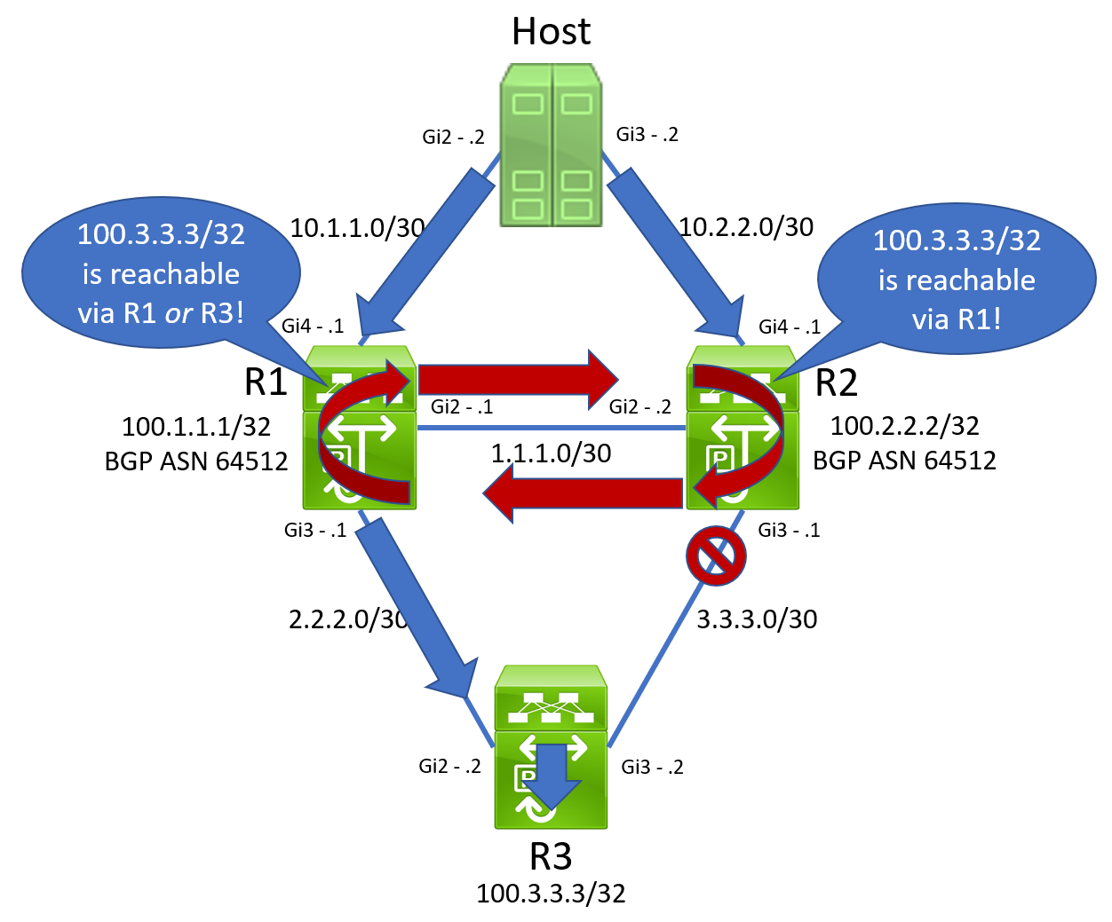
We now have an unfortunate routing loop on our hands. The outage has started, and Christmas is officially ruined. An ICMP Echo ping from Host in our topology no longer works.
1
2
3
4
5
Host#ping 100.3.3.3
Type escape sequence to abort.
Sending 5, 100-byte ICMP Echos to 100.3.3.3, timeout is 2 seconds:
.....
Success rate is 0 percent (0/5)
If we enable ICMP debugs on Host, we can see that an ICMP Time Exceeded message is being received instead of the ICMP Echo Reply packet we expect, suggesting a routing loop is the culprit.
1
2
3
4
5
6
7
8
9
10
11
12
13
14
Host#debug ip icmp
ICMP packet debugging is on
Host#terminal monitor
Host#ping 100.3.3.3
Type escape sequence to abort.
Sending 5, 100-byte ICMP Echos to 100.3.3.3, timeout is 2 seconds:

Mar 20 2022 22:39:42.426: ICMP: time exceeded rcvd from 1.1.1.1.
Mar 20 2022 22:39:44.435: ICMP: time exceeded rcvd from 1.1.1.1.
Mar 20 2022 22:39:46.435: ICMP: time exceeded rcvd from 1.1.1.1.
Mar 20 2022 22:39:48.426: ICMP: time exceeded rcvd from 1.1.1.1.
Mar 20 2022 22:39:50.427: ICMP: time exceeded rcvd from 1.1.1.1.
Success rate is 0 percent (0/5)
Host#
In the customer’s environment, this outage persisted for about 23 minutes. Their outage ended when the ARP adjacency for 3.3.3.2 on R2 did not refresh and eventually dropped from R2’s ARP cache. At this point, R1’s track object 2 transitioned from Up to Down because R1’s IP SLA 2’s reachability to R3 was broken, and the topology reconverged as normal.
Root Cause Analysis
Root Cause Analysis (RCA) is like constructing a jigsaw puzzle, where you piece together small pictures until they form one large image. Sometimes when constructing a jigsaw puzzle, it seems like you’re missing pieces, and it’s difficult to factually say what the big picture is.
Similarly, sometimes when performing RCA, you do not have all of the information needed to declaratively identify the root cause of an issue. However, the facts you do have let you “invent” a fact, assume it is true, and see if it “fits” in the puzzle you’re working with.
In this scenario, let’s assume that the link between R2 and R3 becomes unidirectional. Specifically, traffic sent by R2 to R3 is received by R3 successfully, but traffic sent by R3 to R2 is not received by R2 successfully.
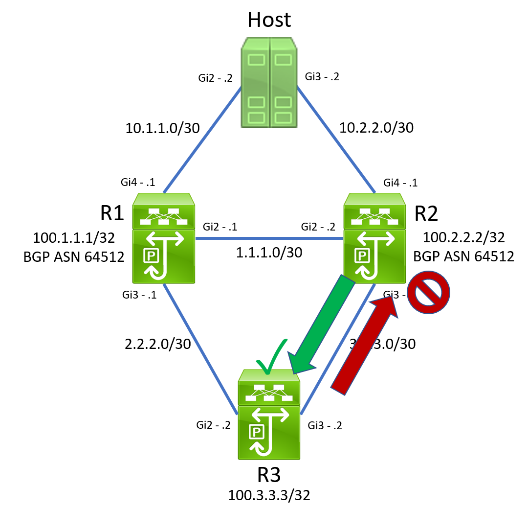
Under this assumption, we would expect R2’s IP SLA 2’s reachability to R3 to go down, as ICMP Echo Reply packets from R3 will not be received by R2.
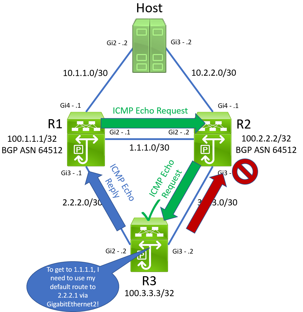
We would also expect R1’s IP SLA 2’s reachability to R3 to go down. When R3 receives an ICMP Echo Request packet from R1 through R3, its default static route pointing through R2 will force it to send ICMP Echo Reply packets out of its GigabitEthernet3 interface towards R2. These packets will not be received by R2 and forwarded along to R1 due to the unidirectional link.
We would also expect R3’s IP SLA 2’s reachability to R3 to go down. R3’s default static route through R2 will be withdrawn, and R3’s default static route through R1 will be inserted in its place.
After this swap in default routes takes place, R3 will continue receiving ICMP Echo Request packets from R1 through the unidirectional link connected to GigabitEthernet3. However, R3’s default static route now points through R1. When R3 receives an ICMP Echo Request sourced from R1’s GigabitEthernet2 interface assigned IP 1.1.1.1, it will follow this default route and send the ICMP Echo Reply out of its GigabitEthernet2 interface towards R1. Furthermore, recall that R3’s GigabitEthernet3 interface is still receiving physical signal, so it is still up/up. This means that R3 can source this ICMP Echo Reply packet from the 3.3.3.2 IP address assigned to GigabitEthernet3 interface, even if the ICMP Echo Reply packet is not leaving via the GigabitEthernet3 interface.
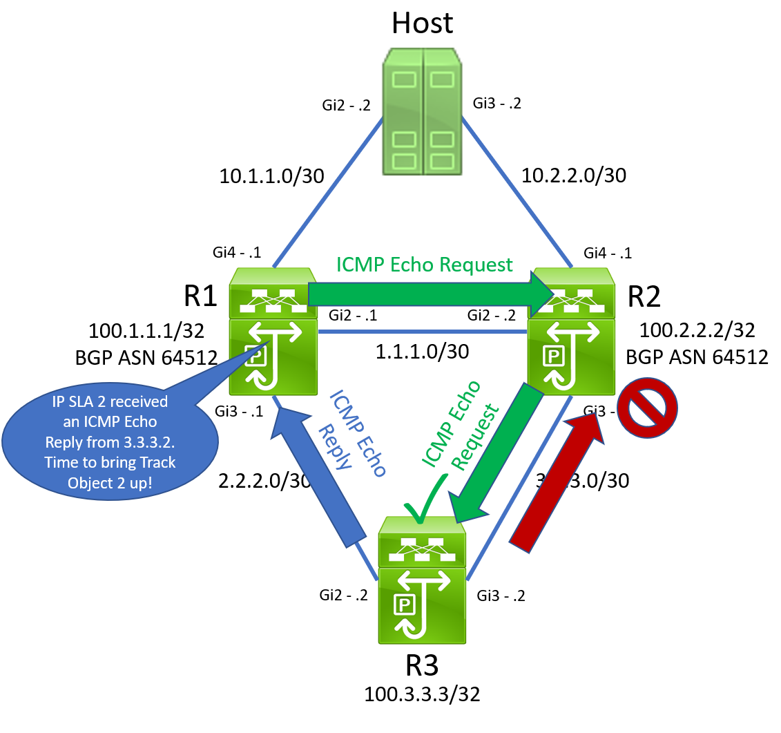
R1 will receive this ICMP Echo Reply packet on its GigabitEthernet3 interface. It will recognize that this packet was in response to an ICMP Echo Request sent by IP SLA 2. R1 doesn’t care that the interface it received this ICMP Echo Reply packet from is different than the interface it originally sent the ICMP Echo Request packet on. R1 just cares that it eventually got a response from somewhere. Therefore, R1 will now state that IP SLA 2’s reachability is good, and R1’s track object 2 will transition from Down to Up.
We have now entered the broken state, as we now have a routing loop. After some time, R2 will attempt to refresh its ARP entry for 3.3.3.2 through its GigabitEthernet3 interface. Since the link is unidirectional, it will not receive the ARP Reply generated by R3. Eventually, R2’s ARP entry for R3’s 3.3.3.2 will expire. R2 cannot forward R1’s ICMP Echo Request packets destined to 3.3.3.2, as it is unable to route the packet and rewrite the Ethernet header with the destination MAC address corresponding to R3’s GigabitEthernet3 interface.
Since R2 is unable to forward R1’s ICMP Echo Request packets, R3 will stop generating ICMP Echo Reply packets in response. R1’s IP SLA 2’s reachability drops, track object 2 goes Down, withdrawing the static route for 100.3.3.3/32 through R2 and breaking the routing loop.
In this customer’s scenario, they were utilizing Cisco Nexus switches, which have a default ARP cache timeout of 25 minutes. This lines up nicely with the 23 minute outage window reported by the customer.
Remember, we don’t know for a fact that a unidirectional link between R2 and R3 is the root cause of this issue. However, when we assume that the link went unidirectional, a lot of the odd behavior observed during the outage is explained perfectly. Our imaginary puzzle piece fits perfectly where it needs to, and the bigger picture becomes clear. After further questioning, we discovered that the link between R2 and R3 (as well as the link between R1 and R3) are WAN links in the customer’s environment. The service provider’s equipment prevented these links from going down outright, but the service provider most likely had some issue with their equipment that caused the link to become unidirectional.
Future Mitigation
The design purpose behind this elaborate combination of IP SLA operations, track objects, and static routes is to establish redundant Layer 3 reachability to a set of prefixes behind a router. In the process, we have essentially reinvented a dynamic unicast routing protocol. Therefore, the long-term solution is to replace this solution with a dynamic unicast routing protocol, such as OSPF or EIGRP.*
*Technically, there may be a valid business or design reason as to why a routing protocol cannot be used over these WAN links - however, I’m not able to think of a valid one off the top of my head.
A short-term solution to this issue is to remove R1’s static route for 100.3.3.3/32 (and corresponding IP SLA/track object) through R2. The iBGP peering between R1 and R2 fulfills reachability advertisement of 100.3.3.3/32 through either R1 or R2 in a failure scenario. In a unidirectional scenario, R2’s IP SLA setup works as expected (that’s why in the broken state, an iBGP route through R1 is installed in R2’s routing table instead of the static route). R1’s static route for 100.3.3.3/32 (and corresponding IP SLA/track object) through R2 is solely responsible for the routing loop.