Cisco Modeling Labs IOS-XE Virtual Router Bootstrap Configuration
Configuration
This is the Cisco IOS-XE configuration I use to bootstrap CSR1000v and Catalyst 8000v virtual routers within Cisco Modeling Labs (CML). Whenever I create a topology involving Cisco IOS-XE virtual routers, this is the minimum set of configuration I use.
1
2
3
4
5
6
7
8
9
10
11
12
13
14
15
16
17
18
19
20
21
22
23
24
25
26
27
28
29
30
31
32
33
34
35
36
37
38
39
40
41
42
43
44
45
46
hostname R1
no ip domain lookup vrf default
aaa new-model
aaa authentication login default local-case
aaa authorization exec default local
username christopher privilege 15 password cisco!123
service timestamps debug datetime msec year
service timestamps log datetime msec year
cdp run
vrf definition management
 !
 address-family ipv4
 exit-address-family
ip domain lookup vrf management source-interface GigabitEthernet1
ip domain name vrf management chrisjhart.net
ntp server vrf management 192.168.10.1
crypto key generate rsa modulus 2048 label RSA_SSH
interface Gi1
 no shutdown
 vrf forwarding management
 ip address dhcp
ip ssh rsa keypair-name RSA_SSH
ip ssh version 2
ip ssh pubkey-chain
 username christopher
  key-string
   AAAAB3NzaC1yc2EAAAADAQABAAABgQDKBXzbkSJHcFWMCcHuHPeHIq0/z+KNNXvO5G+q+HSh45CRXI3fKImCReNfpXlvAxyaW5uZW7FmIYyORyOMX0A2TkCfYVdTee1UkNwoqWsLtovvD3b/nw1pceFA/5K7HXEcodpBTN6s/cF/s0TzrP7tpAZay9
   4HKKWrIqIDdel2q63pKNvId65hQG4H2RmUh4e/NVO6vk4qqrjfv2qzL2LKZUyAsIYtl5O3IC0ATG/SU+7QASaMz1Si3wceaJlRRt9mcUub4ZEH1WJUJY9ggE7+asMURgUYONn9+wU0bhll15vGKEgpXWa24tPZVW22GaxhaJyAilHeRSK/sYovwvjk
   dM6PvzPSuONIOKAGcRDuxAh8mzsVtnYebo09EQJQn5QOSy2YqzYWhqcepPkixAdlL7q04pR1OydONWAAWzfd5ljOIkt8ERlqN5zv2rGlrSOpQzbMAdu3x2rKcw7kcNtyxw5rSqP/PvE2LuaNqkKvaG6qUTqN18Nq+AK1gmhHa+M=
   exit
  key-string
   AAAAB3NzaC1yc2EAAAADAQABAAABgQDQDExDwRYKqyqaAhIr8S8P2YXz4nsUigEiB5us50PCaMtUkt2qxlcT73VVXz6+BjBQ8c0XPS1cbXwZxhTYNiJRMLCdeMDh0Hyk4APLfjdxyoFqZYLso3N86E2KB9gJ0TXyxou335YGo4CrEeni4oo0OmZ/Ud
   YcePIFwUaZXpcmRgObiTexztQxUOe0cQgLk1oPDnsudA5gkTQQpaGZCyS3uO6MUlT6HY/yEZPvqJa72nHdFBGoVad+F2Z22qe8Bj6cb0IYL8X+9FgnmhGrLKzbGF3cZzvSTE3DS/aE73Ue2DygVtjjMOUg1nVqz0hIHonND8PomN11pYVrIMeTXIb0
   YSsDveopeu/y8vUYlWcwaIpaNZhV5/4squv+KS6GzWUbQAqSwqJekvYfFOgk+Vj8wbZuZgDz5epb5uAqyH8CHmNd105iYf1ZzJ0obt2L84/vGzt3XizGEQ/4dKHMIG1MXKZkdQeWhpPv5d4A1lKblvQw0LT/dMFvm4kghowu9Fs=
   exit
ip scp server enable
line con 0
 exec-timeout 0 0
 privilege level 15
 logging synchronous
line vty 0 15
 exec-timeout 0 0
 logging synchronous
 login local
 transport input ssh
end
Usage Instructions
Consider a lab topology in Cisco Modeling Labs (CML) similar to the following, where a Catalyst 8000v virtual router is connected to an Unmanaged Switch node via GigabitEthernet1 and an External Connector node is connected to the Unmanaged Switch node:

Left-click on the Catalyst 8000v virtual router. It will be highlighted in blue, and a menu will appear in the bottom pane.

Left-click on the “Edit Config” tab in the bottom pane menu, if it isn’t selected already. You will see the default bootstrap configuration present. After modifying variable information in the above bootstrap configuration to match your environment (such as router hostname, SSH public keys, and domain name), copy your bootstrap configuration and paste it into the Edit Config text box.
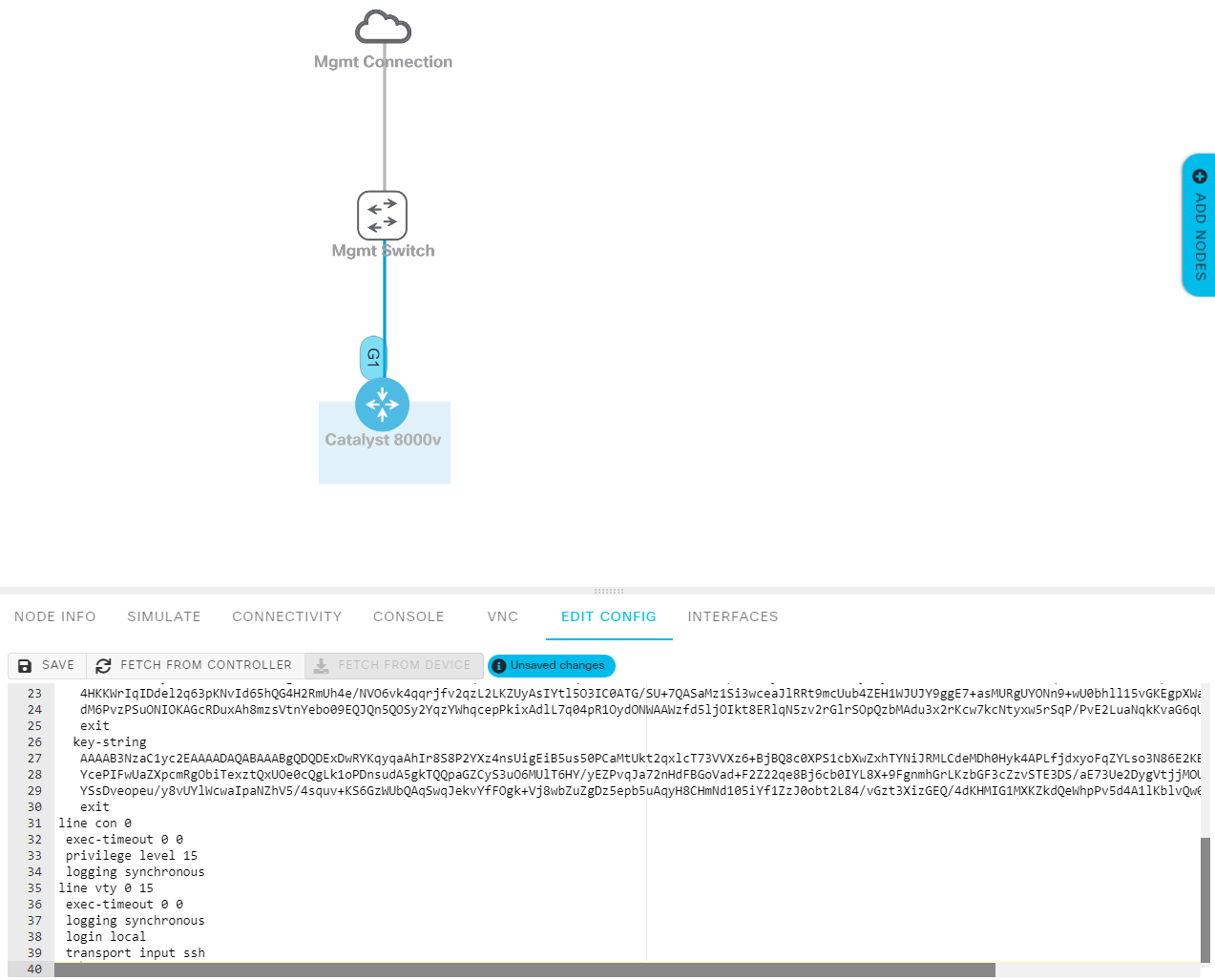
Finally, left-click on the “Save” button just above the bootstrap configuration textbox. Then, start the virtual router by hovering your cursor over it and left-clicking the green “Play” icon.

Configuration Features
This bootstrap configuration has the following key features:
- A dedicated VRF named “management” is created for management purposes. This mimics physical devices that have a dedicated management interface (such as mgmt0 on Nexus switches) and segregates in-band traffic within the topology from management traffic (and vice-versa). Interface GigabitEthernet1 is placed into the management VRF.
- DNS resolution is configured within the management VRF. This lets me access other devices on my network outside of CML using their FQDN (Fully Qualified Domain Name) instead of using the IP address.
- SSH is automatically enabled, and cryptographic keys are automatically generated. This allows us to SSH directly into the virtual router without further configuration.
- In my lab topologies, interface GigabitEthernet1 always connects to an “Unmanaged Switch” node provided by CML. This switch node then connects to an External Connector node configured in Bridge mode. GigabitEthernet1 pulls an IP address via DHCP from my home router, which we can use to SSH directly into the virtual router for further configuration.
- A user account with my name is automatically created, alongside a password (which is rarely used - see the next bullet point for details).
- The public RSA key of two hosts I often use to SSH into virtual routers is imported into the configuration. This way, I can SSH into the virtual router without needing to enter a password. Passwords annoy me! :)
- An NTP server present in my network is automatically configured on each device, ensuring clocks are synchronized between all devices.
- Automatically enables CDP (which is disabled by default on CSR1000v and Catalyst 8000v routers).
- Enables an SCP server on the router, allowing for easy transferring of files into the lab environment.
Tested Virtual Routers
This configuration has been successfully tested on the following nodes:
- CSR1000v running Cisco IOS-XE 16.11.01b
- Catalyst 8000v running Cisco IOS-XE 17.07.01a