Bringing The Gap - Frame Relay
When the ICND1, ICND2, and CCNA R&S composite exams were updated to their latest versions on August 20th, 2016, Frame Relay technology was removed from the exam topics. However, network engineers who obtained their CCNA R&S certification using these new exams and want to pursue their CCNP R&S certification will find that Frame Relay is still in the exam topics under the CCNP ROUTE exam, as well as lingering in the CCIE R&S exam as well! This can make learning an otherwise-legacy technology extremely difficult, especially as there are fewer and fewer real-world examples to draw from.
Fear not! Today we’ll take a deep dive into Frame Relay. We’ll cover how it works, its purpose, what problems it solved, how it can be configured, and how routing protocols need to be configured in order to work over Frame Relay.
Overview - The What & The Why
Frame Relay is a wide-area network, industry-standard data link layer protocol jointly created by a number of companies in the early 1990’s as a replacement for the X.25 WAN protocol. Frame Relay superseded X.25 thanks to its simplicity; it relinquished resource-intensive error correction algorithms in favor of the simpler CRC (cyclic redundancy check) algorithm, allowing for higher performance and greater efficiency. It also lacks explicit flow control procedures, which were made redundant when protocols further up the OSI model implemented similar technologies that were more accurate and efficient; Frame Relay opts for simpler congestion notifications, commonly known as FECN and BECN (which we will discuss later!)
Frame Relay is also a packet-switched WAN technology, which means the service provider’s network is being utilized by multiple customers simultaneously. This lies in stark contrast to traditional circuit-switched WAN technologies such as a leased line, which is a true point-to-point connection between two sites that is not shared by any other customer. The advantage of a packet-switched WAN technology is cost; leased lines tend to be extremely expensive for both the service provider and the end customer. This is primarily because the service provider has to dedicate bandwidth within their infrastructure to you, while with packet-switched WAN technologies, the network is shared between multiple customers at the same time. Since the network is shared, this means that if a few customers are fully utilizing their connections to the service provider, the rest of the customers could potentially be affected through higher latency times or reduced available bandwidth.
Another neat feature that Frame Relay utilizes (although it was not the first protocol to do so) is statistical multiplexing. Statistical multiplexing allows for multiple logical connections to be supported over a single physical connection; furthermore, each logical connection can have a specific amount of bandwidth allocated to it as necessary. For example, if I have a single 256Kbps link with logical connections to four remote sites, I can allocate 128Kbps to a single site, 64Kbps to a second site, and 32Kbps to each of the remaining two sites.
In short, Frame Relay is a protocol that offered a cheaper and more efficient solution to connect remote sites together over a WAN, even over long distances.
Frame Relay Terminology
To begin our conversation on how Frame Relay works and how it can be configured, we need to define some terminology first!
Frame Relay Data Equipment
Like other serial connections, each side of a physical Frame Relay link is one of two things: a DCE, or a DTE.
DCE (Data Circuit-terminating Equipment) is a device typically owned by the Frame Relay service provider that sets the clock (or, in other words, the speed) of the link as well as connect to the rest of the service provider’s network. DCEs are typically Frame Relay packet switches.
DTE (Data Terminal Equipment) are devices typically owned by the customer that accept the parameters (such as the clock speed) provided by the DCE. These devices can be computers, routers, bridges, and other such equipment.
Virtual Circuits
There are two different kinds of circuits that can be defined between Frame Relay devices depending on the type of network connection that is required by the customer.
- VCs (Switched Virtual Circuits) are temporary connections that are dynamically created when data needs to be transferred across the Frame Relay network, and automatically torn down when inactivity is detected.
- For some readers, this behavior should remind you of DMVPN Phase 2/3 spoke-to-spoke tunnels, which are also dynamically created and torn down as traffic necessitates!
- PVCs (Permanent Virtual Circuits) are permanent, predefined connections between remote sites.
It is worth noting that SVCs are not a very popular service – most service providers will only sell PVCs between remote sites at a consistent monthly rate, as opposed to selling an SVC that can only be billed when it is used (which increases the amount of overhead the service provider has to maintain at scale.)
Virtual circuits are differentiated from each other on a device through a unique identifier called a DLCI (Data-Link Connection Identifier, pronounced “dell-see”). The DLCI is locally significant, which means that the value of the DLCI only needs to be unique on each individual router. For some readers, this will sound similar to the OSPF process ID! In most cases, your service provider will tell you what DLCIs to use for each individual circuit.
To demonstrate this, consider the topology below:
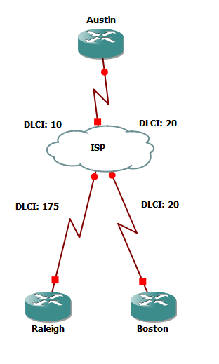
In this example, we have the Austin router with two Frame Relay PVCs, one connected to Raleigh and another connected to Boston. On the Austin side, the ISP has assigned the Austin-Raleigh PVC a DLCI of 10, while the Austin-Boston PVC gets a DLCI of 20. From the ISP’s perspective, they might have multiple other customers that they’ve assigned a DLCI of 10 or 20 to – in fact, one of them is in our diagram! On the Boston side, the Austin-Boston PVC also has a DLCI of 20. However, so long as the ISP handles the switching and routing perspectives of the Frame Relay network (which we will briefly demonstrate later on), there will not be any connectivity issues between the two sites.
Routers can have Frame Relay virtual circuit IPs statically mapped or dynamically discovered for each DLCI. An IP address can be statically mapped to a DLCI using the frame-relay map ip {x.x.x.x} {yyyy} command, where x.x.x.x is the mapped IP address and yyyy is the DLCI the IP address is being mapped to. In this command, the broadcast keyword can be used to specify that broadcast and multicast packets that are received on the interface are to be sent out that same interface using the DLCI specified in the command. Conversely, any DLCI mappings that lack the broadcast keyword will not have any broadcast or multicast packets sent through that DLCI whatsoever, including those originated by the router itself. A common use-case for this is when a routing protocol is in use within the network, as routing protocols will typically form neighborships and advertise routes via multicast packets. Note that the broadcast keyword does not override EIGRP’s split-horizon behavior, where EIGRP will not send advertisements for a route out of an interface if the route was learned on that same interface. This means that when utilizing EIGRP in conjunction with Frame Relay in a hub-and-spoke topology, EIGRP’s split-horizon behavior needs to be disabled on the interface using the no ip split-horizon eigrp {asn} command, where asn is the number chosen for your EIGRP autonomous system.
Alternatively, a router can dynamically discover the IP address of the device on the other end of the virtual circuit. This can be done using the frame-relay interface-dlci {yyyy} command, where yyyy is the DLCI for that particular interface. Routers that dynamically discover the IP address of the device on the other end of the virtual circuit do so using Inverse ARP. Recall from your previous studies that the purpose of ARP is to find the MAC address of the device that holds a specific, known IP address. To be more formal, we have a known Layer 3 address that we wish to map to an unknown Layer 2 address, we use ARP in order to find the unknown Layer 2 address. As the name implies, Inverse ARP does the opposite: we have a known Layer 2 address (a DLCI) that we wish to map to an unknown Layer 3 address (an IP address).
The output below demonstrates the Inverse ARP process through the lens of the debug frame-relay packet command after attempting to ping the IP address of the device on the other side of the virtual circuit:
1
2
3
4
5
6
7
8
9
10
11
12
13
14
15
16
17
18
19
20
21
22
23
24
Router#ping 1.1.1.10

Type escape sequence to abort.
Sending 5, 100-byte ICMP Echos to 1.1.1.10, timeout is 2 seconds:

.!!!!!

Success rate is 80 percent (4/5), round-trip min/avg/max = 16/25/36 ms

*Mar 1 04:27:52.366: Serial1/0:Encaps failed--no map entry link 7(IP)
*Mar 1 04:27:53.674: Serial1/0(o): dlci 110(0x18E1), pkt encaps 0x0300 0x8000 0x0000 0x806 (ARP), datagramsize 34
*Mar 1 04:27:53.674: FR: Sending INARP Request on interface Serial1/0 dlci 110 for link 7(IP)
*Mar 1 04:27:53.758: broadcast dequeue
*Mar 1 04:27:53.758: Serial1/0(o):Pkt sent on dlci 110(0x18E1), pkt encaps 0x300 0x8000 0x0 0x806 (ARP), datagramsize 34
*Mar 1 04:27:53.790: Serial1/0(i): dlci 110(0x18E1), pkt encaps 0x0300 0x8000 0x0000 0x806 (ARP), datagramsize 34
*Mar 1 04:27:53.794: Serial1/0: frame relay INARP received
*Mar 1 04:27:54.366: Serial1/0(o): dlci 110(0x18E1), pkt type 0x800(IP), datagramsize 104
*Mar 1 04:27:54.390: Serial1/0(i): dlci 110(0x18E1), pkt type 0x800, datagramsize 104
*Mar 1 04:27:54.394: Serial1/0(o): dlci 110(0x18E1), pkt type 0x800(IP), datagramsize 104
*Mar 1 04:27:54.410: Serial1/0(i): dlci 110(0x18E1), pkt type 0x800, datagramsize 104
*Mar 1 04:27:54.418: Serial1/0(o): dlci 110(0x18E1), pkt type 0x800(IP), datagramsize 104
*Mar 1 04:27:54.454: Serial1/0(i): dlci 110(0x18E1), pkt type 0x800, datagramsize 104
*Mar 1 04:27:54.454: Serial1/0(o): dlci 110(0x18E1), pkt type 0x800(IP), datagramsize 104
*Mar 1 04:27:54.470: Serial1/0(i): dlci 110(0x18E1), pkt type 0x800, datagramsize 104
In particular, note how the router logs Encaps failed–no map entry link 7(IP), indicating that it does not have an IP address for this DLCI. Soon afterwards, it sends out an INARP Request message containing DLCI 110 as the Layer 2 address to be referenced by the remote router. Just afterwards, it receives an INARP Reply containing the Layer 3 IP address, and using this new information, it is able to send the remaining pings through the circuit.
DLCIs that dynamically discover Layer 3 addresses using Inverse ARP will also forward any multicast or broadcast frames through that DLCI by default.
Enhancements
Cisco, StrataCom, Northern Telecom, and Digital Equipment Corporation came together in 1990 to create a number of additional features, functionality, and manageability to Frame Relay in a set of enhancements named LMI (Local Management Interface). One of the most significant of these enhancements are virtual circuit status messages between DTE devices and DCE devices. Simply put, a customer’s Frame Relay router and a service provider’s Frame Relay switch need a way to communicate with one another to report on the status and health of PVCs, and the LMI provides that functionality. The customer’s Frame Relay router sends out status-enquiry (or StEnq) messages every 10 seconds to the Frame Relay switch, which replies with status messages confirming the health of the link. Once every 60 seconds, the Frame Relay switch will respond with a full status message listing information about all of the known DLCIs. You can read more about the LMI messages and message format here. Below shows the output of debug frame-relay lmi on a healthy Frame Relay link, showing a normal status reply as well as a full status reply:
1
2
3
4
5
6
7
8
9
10
11
12
13
14
15
16
17
18
19
20
*Mar 1 03:14:46.447: Serial1/0(out): StEnq, myseq 255, yourseen 254, DTE up
*Mar 1 03:14:46.447: datagramstart = 0xF401614, datagramsize = 13
*Mar 1 03:14:46.447: FR encap = 0xFCF10309
*Mar 1 03:14:46.447: 00 75 01 01 01 03 02 FF FE
*Mar 1 03:14:46.451:
*Mar 1 03:14:46.467: Serial1/0(in): Status, myseq 255, pak size 13
*Mar 1 03:14:46.467: RT IE 1, length 1, type 1
*Mar 1 03:14:46.467: KA IE 3, length 2, yourseq 255, myseq 255
Router#
*Mar 1 03:14:56.447: Serial1/0(out): StEnq, myseq 1, yourseen 255, DTE up
*Mar 1 03:14:56.447: datagramstart = 0xF401894, datagramsize = 13
*Mar 1 03:14:56.447: FR encap = 0xFCF10309
*Mar 1 03:14:56.447: 00 75 01 01 00 03 02 01 FF
*Mar 1 03:14:56.451:
*Mar 1 03:14:56.483: Serial1/0(in): Status, myseq 1, pak size 37
*Mar 1 03:14:56.483: RT IE 1, length 1, type 0
*Mar 1 03:14:56.483: KA IE 3, length 2, yourseq 1 , myseq 1
*Mar 1 03:14:56.483: PVC IE 0x7 , length 0x6 , dlci 101, status 0x2 , bw 0
*Mar 1 03:14:56.483: PVC IE 0x7 , length 0x6 , dlci 102, status 0x2 , bw 0
*Mar 1 03:14:56.487: PVC IE 0x7 , length 0x6 , dlci 103, status 0x2 , bw 0
Congestion
Frame Relay utilizes a simple built-in congestion notification system through three bits in the Address field of the frame. These bits can be flipped by Frame Relay switches while forwarding traffic to indicate to two devices (the device sending traffic, and the device receiving traffic) whether the path being used between the two is congested or not. Under normal, healthy conditions, all three of these bits remain set at 0. The three bits correspond to three different notifications: FECN, BECN, and DE.
FECN (Forward-Explicit Congestion Notification) is the first bit among the three. If this bit is set to 1 by a Frame Relay switch, it serves as a message to the destination device that the path that was used to send the frame is currently congested.
BECN (Backward-Explicit Congestion Notification) is the second bit among the three. If this bit is set to 1 by a Frame Relay switch, it serves as a message to the source device that the path that was used to send the frame is currently congested.
DE (Discard Eligibility) is the third bit among the three. If this bit is set to 1 by a DTE device (such as a router, host, etc.), then it indicates to a Frame Relay switch that it is a low-priority frame and can be dropped if there are congestion issues along the frame’s path.
FECN and BECN can be very easy to confuse, since the only difference between the two is which specific bit is set, and which device is receiving the frame with the bit set. If you think of a frame as moving through the network from a source to a destination, a frame moves forward to the destination, while it would need to move backward to get to the source. Frames with FECN and BECN bits set are normally sent at the exact same time. The easiest way to identify how many frames have been received with FECN, BECN, and DE bits set is through the show frame-relay pvc command, shown below.
1
2
3
4
5
6
7
8
9
10
11
12
13
14
15
16
17
18
19
20
Router#show frame pvc

PVC Statistics for interface Serial1/0 (Frame Relay DTE)

Active Inactive Deleted Static
 Local 1 0 0 0
 Switched 0 0 0 0
 Unused 0 0 0 0

DLCI = 110, DLCI USAGE = LOCAL, PVC STATUS = ACTIVE, INTERFACE = Serial1/0.10

input pkts 22635 output pkts 25877 in bytes 2244345
 out bytes 3324994 dropped pkts 0 in pkts dropped 0
 out pkts dropped 0 out bytes dropped 0
 in FECN pkts 0 in BECN pkts 0 out FECN pkts 0
 out BECN pkts 0 in DE pkts 0 out DE pkts 0
 out bcast pkts 25520 out bcast bytes 2966834
 5 minute input rate 11000 bits/sec, 0 packets/sec
 5 minute output rate 11000 bits/sec, 0 packets/sec
 pvc create time 2d09h, last time pvc status changed 2d09h
This congestion notification system is simple for a good reason. Complex congestion detection and mitigation adds overhead to the protocol which causes reduced efficiency. Furthermore, in today’s networks, congestion detection and mitigation has been moved to the upper levels of the networking stack – TCP’s built-in windowing serves as a great example of this migration away from Layer 2 congestion handling.
Frame Relay Configuration
Now, it’s time for the fun stuff! We’re going to configure the topology below.
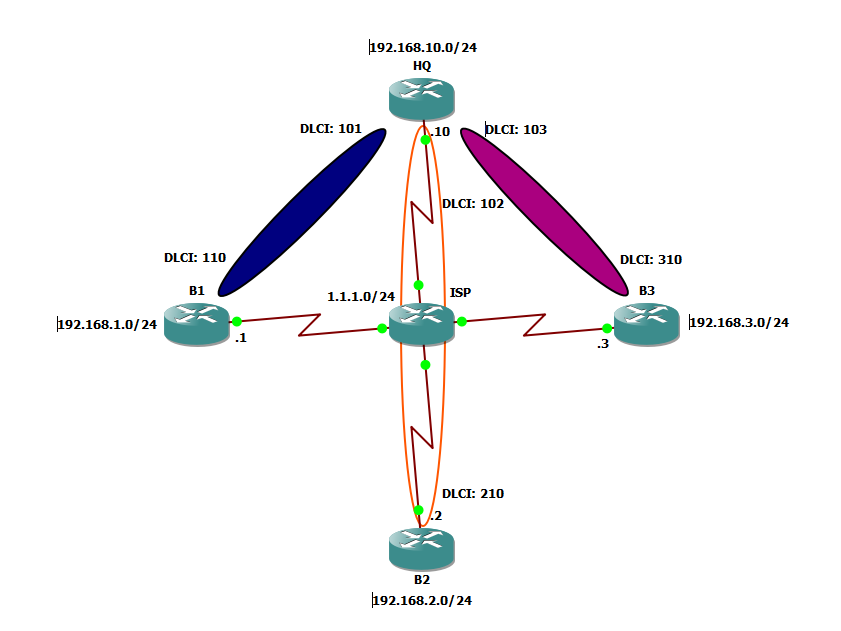
This topology features a total of four routers, with one router located at a headquarters site and the other three routers at branch sites. Each router has a local /24 network, simulated using a loopback interface. All sites are connected to each other via a Frame Relay switch, which we will also configure. The end goal of our first lab will be to create PVCs between each branch router and the HQ router, then exchange local routes using a routing protocol.
First, let’s configure the serial interfaces of each branch router as well as the HQ router. Each branch router will dynamically discover the IP address of the HQ router’s serial interface, while the HQ router will statically map each branch router’s IP address to a DLCI.
1
2
3
4
5
6
7
8
9
10
11
12
13
14
15
16
17
18
19
20
21
22
23
24
25
26
27
28
29
30
31
32
33
34
35
B1#conf t
Enter configuration commands, one per line. End with CNTL/Z.
B1(config)#interface Serial1/0
B1(config-if)#ip address 1.1.1.1 255.255.255.0
B1(config-if)#encapsulation frame-relay
B1(config-if)#frame-relay interface-dlci 110

###############################

B2#conf t
Enter configuration commands, one per line. End with CNTL/Z.
B2(config)#interface Serial1/0
B2(config-if)#ip address 1.1.1.2 255.255.255.0
B2(config-if)#encapsulation frame-relay
B2(config-if)#frame-relay interface-dlci 210

###############################

B3#conf t
Enter configuration commands, one per line. End with CNTL/Z.
B3(config)#interface Serial1/0
B3(config-if)#ip address 1.1.1.3 255.255.255.0
B3(config-if)#encapsulation frame-relay
B3(config-if)#frame-relay interface-dlci 310

###############################

HQ#conf t
Enter configuration commands, one per line. End with CNTL/Z.
HQ(config)#interface Serial1/0
HQ(config-if)#ip address 1.1.1.10 255.255.255.0
HQ(config-if)#encapsulation frame-relay
HQ(config-if)#frame-relay map ip 1.1.1.1 101 broadcast
HQ(config-if)#frame-relay map ip 1.1.1.2 102 broadcast
HQ(config-if)#frame-relay map ip 1.1.1.3 103 broadcast
Note that for the HQ router, each static mapping contains the broadcast keyword. As discussed before, this will allow broadcast and multicast packets received on each DLCI to be rebroadcasted back out to each of the remaining DLCIs. This will also facilitate our routing protocol configuration later on.
Next, let’s finish establishing basic Frame Relay connectivity by configuring our Frame Relay switch.
1
2
3
4
5
6
7
8
9
10
11
12
13
14
15
16
17
18
19
20
21
22
23
ISP#conf t
Enter configuration commands, one per line. End with CNTL/Z.
ISP(config)#frame-relay switching
ISP(config)#interface Serial1/0
ISP(config-if)#encapsulation frame-relay
ISP(config-if)#frame-relay intf-type dce
ISP(config-if)#frame-relay route 110 interface Serial1/1 101
ISP(config-if)#exit
ISP(config)#interface Serial1/1
ISP(config-if)#interface Serial1/1
ISP(config-if)#encapsulation frame-relay
ISP(config-if)#frame-relay intf-type dce
ISP(config-if)#frame-relay route 101 interface Serial1/0 110
ISP(config-if)#frame-relay route 102 interface Serial1/3 210
ISP(config-if)#frame-relay route 103 interface Serial1/2 310
ISP(config-if)#interface Serial1/2
ISP(config-if)#encapsulation frame-relay
ISP(config-if)#frame-relay intf-type dce
ISP(config-if)#frame-relay route 310 interface Serial1/1 103
ISP(config-if)#interface Serial1/3
ISP(config-if)#encapsulation frame-relay
ISP(config-if)#frame-relay intf-type dce
ISP(config-if)#frame-relay route 210 interface Serial1/1 102
This configuration gleans a small idea as to how a service provider must configure their Frame Relay infrastructure in order to provide connectivity between a customer’s sites. Each customer-facing interface must be configured to be a DCE interface, so that the service provider controls the clock rate and is able to enforce the CIR (Committed Information Rate) that the customer is paying for. Each customer-facing interface also must contain a frame-relay route statement, indicating:
- The DLCI of the interface
- The egress interface that ingress frames should be sent to
- The DLCI to be used for the egress interface.
Now, our HQ router should be able to ping each of the branch routers without issue. You may need to try this command a few times before connectivity is established due to Inverse ARP dynamically discovering the IP address of our HQ router.
1
2
3
4
5
6
7
8
9
10
11
12
13
14
15
16
17
18
HQ#ping 1.1.1.1

Type escape sequence to abort.
Sending 5, 100-byte ICMP Echos to 1.1.1.1, timeout is 2 seconds:
!!!!!
Success rate is 100 percent (5/5), round-trip min/avg/max = 16/20/28 ms
HQ#ping 1.1.1.2

Type escape sequence to abort.
Sending 5, 100-byte ICMP Echos to 1.1.1.2, timeout is 2 seconds:
!!!!!
Success rate is 100 percent (5/5), round-trip min/avg/max = 12/17/20 ms
HQ#ping 1.1.1.3

Type escape sequence to abort.
Sending 5, 100-byte ICMP Echos to 1.1.1.3, timeout is 2 seconds:
!!!!!
Success rate is 100 percent (5/5), round-trip min/avg/max = 8/20/28 ms
Lastly, let’s configure EIGRP across all of our routers.
1
2
3
4
5
6
7
8
9
10
11
12
13
14
15
16
17
18
19
20
21
22
23
B1(config)#router eigrp 1
B1(config-router)#network 1.1.1.0 0.0.0.255
B1(config-router)#network 192.168.1.0 0.0.0.255

###############################

B2(config)#router eigrp 1
B2(config-router)#network 1.1.1.0 0.0.0.255
B2(config-router)#network 192.168.2.0 0.0.0.255

#########################

B3(config)#router eigrp 1
B3(config-router)#network 1.1.1.0 0.0.0.255
B3(config-router)#network 192.168.3.0 0.0.0.255

#########################

HQ(config)#router eigrp 1
HQ(config-router)#network 1.1.1.0 0.0.0.255
HQ(config-router)#network 192.168.10.0 0.0.0.255
HQ(config-router)#interface Serial1/0
HQ(config-if)#no ip split-horizon eigrp 1
Of course, never forget to verify all of your neighbors are up, and that routes have been exchanged across all routers as expected!
1
2
3
4
5
6
7
8
9
10
11
12
13
14
15
16
17
18
19
20
21
22
23
24
25
26
27
28
29
30
31
32
33
34
35
36
37
38
39
40
41
42
43
44
45
46
47
HQ#show ip eigrp neighbors
IP-EIGRP neighbors for process 1
H Address Interface Hold Uptime SRTT RTO Q Seq
 (sec) (ms) Cnt Num
2 1.1.1.3 Se1/0 163 00:21:01 42 252 0 6
1 1.1.1.2 Se1/0 150 01:46:34 40 240 0 7
0 1.1.1.1 Se1/0 170 01:47:04 429 2574 0 7


HQ#show ip route
Codes: C - connected, S - static, R - RIP, M - mobile, B - BGP
 D - EIGRP, EX - EIGRP external, O - OSPF, IA - OSPF inter area
 N1 - OSPF NSSA external type 1, N2 - OSPF NSSA external type 2
 E1 - OSPF external type 1, E2 - OSPF external type 2
 i - IS-IS, su - IS-IS summary, L1 - IS-IS level-1, L2 - IS-IS level-2
 ia - IS-IS inter area, * - candidate default, U - per-user static route
 o - ODR, P - periodic downloaded static route

Gateway of last resort is not set

1.0.0.0/8 is variably subnetted, 2 subnets, 2 masks
C 1.1.1.0/24 is directly connected, Serial1/0
D 1.0.0.0/8 is a summary, 00:23:00, Null0
C 192.168.10.0/24 is directly connected, Loopback0
D 192.168.1.0/24 [90/2297856] via 1.1.1.1, 00:23:27, Serial1/0
D 192.168.2.0/24 [90/2297856] via 1.1.1.2, 00:23:18, Serial1/0
D 192.168.3.0/24 [90/2297856] via 1.1.1.3, 00:21:56, Serial1/0


B1#show ip route
Codes: C - connected, S - static, R - RIP, M - mobile, B - BGP
 D - EIGRP, EX - EIGRP external, O - OSPF, IA - OSPF inter area
 N1 - OSPF NSSA external type 1, N2 - OSPF NSSA external type 2
 E1 - OSPF external type 1, E2 - OSPF external type 2
 i - IS-IS, su - IS-IS summary, L1 - IS-IS level-1, L2 - IS-IS level-2
 ia - IS-IS inter area, * - candidate default, U - per-user static route
 o - ODR, P - periodic downloaded static route

Gateway of last resort is not set

1.0.0.0/8 is variably subnetted, 2 subnets, 2 masks
C 1.1.1.0/24 is directly connected, Serial1/0
D 1.0.0.0/8 is a summary, 00:23:44, Null0
D 192.168.10.0/24 [90/2297856] via 1.1.1.10, 00:23:18, Serial1/0
C 192.168.1.0/24 is directly connected, Loopback0
D 192.168.2.0/24 [90/2809856] via 1.1.1.10, 00:20:53, Serial1/0
D 192.168.3.0/24 [90/2809856] via 1.1.1.10, 00:20:53, Serial1/0
It looks like EIGRP is up and running! Now, after all that hard work, let’s rip it out and test our Frame Relay WAN with OSPF instead.
1
2
3
4
5
6
7
8
9
10
11
12
13
14
15
16
17
18
19
20
21
22
23
24
25
B1(config)#no router eigrp 1
B1(config)#router ospf 1
B1(config-router)#network 192.168.1.0 0.0.0.255 area 0
B1(config-router)#network 1.1.1.0 0.0.0.255 area 0

#########################

B2(config)#no router eigrp 1
B2(config)#router ospf 1
B2(config-router)#network 1.1.1.0 0.0.0.255 area 0
B2(config-router)#network 192.168.2.0 0.0.0.255 area 0

#########################

B3(config)#no router eigrp 1
B3(config)#router ospf 1
B3(config-router)#network 192.168.3.0 0.0.0.255 area 0
B3(config-router)#network 1.1.1.0 0.0.0.255 area 0

#########################

HQ(config)#no router eigrp 1
HQ(config)#router ospf 1
HQ(config-router)#network 192.168.10.0 0.0.0.255 area 0
HQ(config-router)#network 1.1.1.0 0.0.0.255 area 0
You will notice that after waiting about a minute, no OSPF neighbors on any of the routers are detected. This is because when OSPF was enabled on the Serial1/0 interface with the network command, it detected that Frame Relay was enabled on the interface and defaulted its network type to NBMA (NonBroadcast MultiAccess). This can be confirmed with the show ip ospf interface command:
1
2
3
4
B1#show ip ospf interface Serial1/0
 Serial1/0 is up, line protocol is up
 Internet Address 1.1.1.1/24, Area 0
 Process ID 1, Router ID 192.168.1.1, Network Type NON_BROADCAST, Cost: 64
Under this network type, OSPF does not send multicast Hello packets out of Serial1/0, and without another router receiving any Hello packets, we’ll never have an OSPF neighborship form! In order to form neighborships with our other routers, we have one of two options, depending on how we have configured Frame Relay throughout our network.
Dynamic Neighborships
Think back to when we configured Frame Relay on the Serial1/0 interface of HQ. We added the broadcast keyword on each of the DLCIs, which allows for multicast and broadcast packets to egress each of those DLCIs. On each branch router, we’re also dynamically discovering the Layer 3 address of each DLCI using Inverse ARP, which also allows for the egress of multicast and broadcast packets. Because of these previous decisions, our Frame Relay WAN is effectively acting the same as a broadcast network. The only thing we need to do on each router is change the OSPF network type of the serial interfaces to reflect this behavior!
1
2
3
4
5
6
7
8
9
10
11
12
13
14
15
16
17
HQ(config)#interface Serial1/0
HQ(config-if)#ip ospf network broadcast

#########################

B1(config)#interface Serial1/0
B1(config-if)#ip ospf network broadcast

#########################

B2(config)#interface Serial1/0
B2(config-if)#ip ospf network broadcast

#########################

B3(config)#interface Serial1/0
B3(config-if)#ip ospf network broadcast
After a few seconds, all OSPF neighbors should come up, and routes should be populated in the routing table!
1
2
3
4
5
6
7
8
9
10
11
12
13
14
15
16
17
18
19
20
21
22
23
24
25
26
27
28
HQ#show ip ospf neighbor

Neighbor ID Pri State Dead Time Address Interface
192.168.1.1 1 FULL/DROTHER 00:00:31 1.1.1.1 Serial1/0
192.168.2.1 1 FULL/DROTHER 00:00:32 1.1.1.2 Serial1/0
192.168.3.1 1 FULL/BDR 00:00:39 1.1.1.3 Serial1/0


HQ#show ip route
Codes: C - connected, S - static, R - RIP, M - mobile, B - BGP
 D - EIGRP, EX - EIGRP external, O - OSPF, IA - OSPF inter area
 N1 - OSPF NSSA external type 1, N2 - OSPF NSSA external type 2
 E1 - OSPF external type 1, E2 - OSPF external type 2
 i - IS-IS, su - IS-IS summary, L1 - IS-IS level-1, L2 - IS-IS level-2
 ia - IS-IS inter area, * - candidate default, U - per-user static route
 o - ODR, P - periodic downloaded static route

Gateway of last resort is not set

1.0.0.0/24 is subnetted, 1 subnets
C 1.1.1.0 is directly connected, Serial1/0
C 192.168.10.0/24 is directly connected, Loopback0
 192.168.1.0/32 is subnetted, 1 subnets
O 192.168.1.1 [110/65] via 1.1.1.1, 01:16:17, Serial1/0
 192.168.2.0/32 is subnetted, 1 subnets
O 192.168.2.1 [110/65] via 1.1.1.2, 01:09:06, Serial1/0
 192.168.3.0/32 is subnetted, 1 subnets
O 192.168.3.1 [110/65] via 1.1.1.3, 01:08:56, Serial1/0
Those of you who are familiar with OSPF should notice something about this output. From the HQ router’s perspective, it is FULL with each router, but we only have a single neighbor that is claiming to be a BDR, while the other two are DROTHERs. Let’s investigate some more!
1
2
3
4
5
6
7
8
9
10
11
12
13
14
15
16
17
HQ#show ip ospf neighbor 192.168.1.1
 Neighbor 192.168.1.1, interface address 1.1.1.1
 In the area 0 via interface Serial1/0
 Neighbor priority is 1, State is FULL, 408 state changes
 DR is 1.1.1.10 BDR is 1.1.1.1

HQ#show ip ospf neighbor 192.168.2.1
 Neighbor 192.168.2.1, interface address 1.1.1.2
 In the area 0 via interface Serial1/0
 Neighbor priority is 1, State is FULL, 6 state changes
 DR is 1.1.1.10 BDR is 1.1.1.2

HQ#show ip ospf neighbor 192.168.3.1
 Neighbor 192.168.3.1, interface address 1.1.1.3
 In the area 0 via interface Serial1/0
 Neighbor priority is 1, State is FULL, 6 state changes
 DR is 1.1.1.10 BDR is 1.1.1.3
This is interesting – how come when we look at the full OSPF neighbor table, we have one BDR and two DROTHERs, but when we look at each neighbor individually, each neighbor claims to be a BDR?
Well, let’s go off on a tangent about OSPF’s DR/BDR election process real quick. In a traditional broadcast multiaccess environment, each router would have an interface active in the 1.1.1.0/24 network. Since we have more than one router connected to the same network, we need to elect a DR and BDR to represent the network through a Type 2 LSA. All OSPF routers compare priorities with each other and eventually settle on a DR and a BDR.
However, in our network, not all routers can talk to each other. Each branch router only has a PVC with the HQ hub router, and is only able to communicate directly with the hub – branches cannot communicate directly with each other. Because the HQ router happens to have the highest priority out of all of them (it has the highest IPv4 up/up loopback interface, which is the first tiebreaker for choosing a router ID, the highest of which is used to determine the DR in a DR/BDR election when all OSPF priority values match), all branch routers unanimously (although independently, since they can’t speak with each other) choose HQ as its DR. Next, we need to choose our BDR, which is the second-highest router ID on the network. The HQ router can communicate with all three branches, and clearly sees that B3 wins the BDR election with a router ID of 192.168.3.1. However, the three branch routers cannot communicate with each other, so they’re unaware that anybody else is on the 1.1.1.0/24 network aside from themselves and the HQ router. Because the HQ router is the DR, and each branch believe it is the only other router on the network, each branch claims to be the BDR for the network.
This behavior is reflected in our output above! The show ip ospf neighbor command displays what the local router (that is, the router that the command is executed on) believes to be true regarding its OSPF neighborships. However, the show ip ospf neighbor {x.x.x.x} (where x.x.x.x is the router ID of an OSPF neighbor) command shows what that specific neighbor believes to be true regarding the OSPF neighborship.
The solution to this problem is documented in the Initial Configurations for OSPF over Frame Relay Subinterfaces guide:
“…additional configuration is necessary in a hub and spoke topology to make sure that the hub routers, which have connectivity with every other spoke router, are elected as the DR and BDR. Alternatively, you can change the configuration on the NBMA interface to make OSPF believe that it is another network type that does not have these problems.”
This “additional configuration” is the manual configuration of OSPF priority values on each router, such that the hub routers (if there are more than one) are the only routers configured to participate in the DR/BDR election. Spoke routers should be configured such that they do not participate in DR/BDR elections at all.
1
2
3
4
5
6
7
8
9
10
11
12
13
14
15
16
B1(config)#interface Serial1/0
B1(config-if)#ip ospf priority 0

#########################
B2(config)#interface Serial1/0
B2(config-if)#ip ospf priority 0

#########################

B3(config)#interface Serial1/0
B3(config-if)#ip ospf priority 0

#########################

HQ(config)#interface Serial1/0
HQ(config-if)#ip ospf priority 255
Now, let’s review the same show ip ospf neighbor command as we did before to verify our issue is resolved:
1
2
3
4
5
6
7
8
9
10
11
12
13
14
15
16
17
18
19
20
21
22
23
24
HQ#show ip ospf neighbor

Neighbor ID Pri State Dead Time Address Interface
192.168.1.1 0 FULL/DROTHER 00:00:37 1.1.1.1 Serial1/0
192.168.2.1 0 FULL/DROTHER 00:00:38 1.1.1.2 Serial1/0
192.168.3.1 0 FULL/DROTHER 00:00:39 1.1.1.3 Serial1/0

HQ#show ip ospf neighbor 192.168.1.1
 Neighbor 192.168.1.1, interface address 1.1.1.1
 In the area 0 via interface Serial1/0
 Neighbor priority is 0, State is FULL, 408 state changes
 DR is 1.1.1.10 BDR is 0.0.0.0

HQ#show ip ospf neighbor 192.168.2.1
 Neighbor 192.168.2.1, interface address 1.1.1.2
 In the area 0 via interface Serial1/0
 Neighbor priority is 0, State is FULL, 6 state changes
 DR is 1.1.1.10 BDR is 0.0.0.0

HQ#show ip ospf neighbor 192.168.3.1
 Neighbor 192.168.3.1, interface address 1.1.1.3
 In the area 0 via interface Serial1/0
 Neighbor priority is 0, State is FULL, 6 state changes
 DR is 1.1.1.10 BDR is 0.0.0.0
There we go! Now that we’ve resolved that issue, let’s return to playing with Frame Relay configuration by experimenting with the broadcast keyword in the frame-relay map ip command. As we talked about earlier, the broadcast keyword allows for multicast and broadcast frames to egress out of the mapped DLCI. What happens if we remove that keyword from the command for B1’s DLCI?
1
2
3
HQ(config)#interface Serial1/0
HQ(config-if)#no frame-relay map ip 1.1.1.1 101 broadcast
HQ(config-if)#frame-relay map ip 1.1.1.1 101
After a short time, the OSPF neighborship on the HQ router starts flapping:
1
2
3
*Mar 1 13:57:07.848: %OSPF-5-ADJCHG: Process 1, Nbr 192.168.1.1 on Serial1/0 from LOADING to FULL, Loading Done
*Mar 1 13:57:55.784: %OSPF-5-ADJCHG: Process 1, Nbr 192.168.1.1 on Serial1/0 from LOADING to FULL, Loading Done
*Mar 1 13:58:44.008: %OSPF-5-ADJCHG: Process 1, Nbr 192.168.1.1 on Serial1/0 from LOADING to FULL, Loading Done
This behavior also manifests on B1:
1
2
3
4
5
6
*Mar 1 13:59:10.376: %OSPF-5-ADJCHG: Process 1, Nbr 192.168.10.1 on Serial1/0 from FULL to DOWN, Neighbor Down: Dead timer expired
*Mar 1 13:59:17.504: %OSPF-5-ADJCHG: Process 1, Nbr 192.168.10.1 on Serial1/0 from LOADING to FULL, Loading Done
*Mar 1 14:00:02.632: %OSPF-5-ADJCHG: Process 1, Nbr 192.168.10.1 on Serial1/0 from FULL to DOWN, Neighbor Down: Dead timer expired
*Mar 1 14:00:05.428: %OSPF-5-ADJCHG: Process 1, Nbr 192.168.10.1 on Serial1/0 from LOADING to FULL, Loading Done
*Mar 1 14:00:52.988: %OSPF-5-ADJCHG: Process 1, Nbr 192.168.10.1 on Serial1/0 from FULL to DOWN, Neighbor Down: Dead timer expired
*Mar 1 14:00:53.648: %OSPF-5-ADJCHG: Process 1, Nbr 192.168.10.1 on Serial1/0 from LOADING to FULL, Loading Done
Let’s think about what’s happening here. HQ can no longer send multicast or broadcast to B1’s DLCI, but it can still receive multicast and broadcast traffic from B1. B1 continues to send multicast OSPF Hello packets to HQ, but HQ is unable to send a multicast OSPF Hello packet in reply. Traditionally, OSPF routers will exchange Hello packets and quickly move their neighborship states from DOWN to INIT to 2-WAY, then transition to EXSTART as they begin exchanging DBD packets. However, OSPF routers can also skip the INIT state and go straight to 2-WAY if they receive DBD packets from a neighbor in the INIT state (or, in other words, if they receive DBD messages on an interface they’ve sent an OSPF Hello packet out of).
HQ cannot send multicast or broadcast packets, but luckily, DBD packets (as well as LSRs, LSUs, and LSAcks) are unicast in nature, and B1 has identified its IP address in the Hello packet it was able to send to HQ. Therefore, the two routers are able to form a neighborship and progress to a FULL state. However, in OSPF, multicast Hello packets are also used as a keepalive between neighbors. Because HQ is unable to send these keepalive messages to B1, B1 eventually declares the HQ dead and tears down the neighborship. However, B1 continues to send multicast Hello packets out of the HQ PVC, and so the whole process starts over again.
Static Neighborships
If changing the OSPF network type from NBMA to broadcast doesn’t suit your fancy, we’ll need to configure static OSPF neighbors for each of the PVCs. Keep in mind that OSPF DR/BDR elections occur on NBMA networks as well, so we will need to retain our OSPF priority configuration from our previous adventure with dynamic neighborships.
1
2
3
4
5
6
7
8
9
10
11
12
13
14
15
16
17
18
19
B1(config)#router ospf 1
B1(config-router)#neighbor 1.1.1.10

#########################

B2(config)#router ospf 1
B2(config-router)#neighbor 1.1.1.10

#########################

B3(config)#router ospf 1
B3(config-router)#neighbor 1.1.1.10

#########################

HQ(config)#router ospf 1
HQ(config-router)#neighbor 1.1.1.1
HQ(config-router)#neighbor 1.1.1.2
HQ(config-router)#neighbor 1.1.1.3
Shortly afterwards, we will see neighborships form on the HQ router.
1
2
3
*Mar 1 14:39:56.524: %OSPF-5-ADJCHG: Process 1, Nbr 192.168.3.1 on Serial1/0 from LOADING to FULL, Loading Done
*Mar 1 14:39:56.528: %OSPF-5-ADJCHG: Process 1, Nbr 192.168.1.1 on Serial1/0 from LOADING to FULL, Loading Done
*Mar 1 14:39:56.532: %OSPF-5-ADJCHG: Process 1, Nbr 192.168.2.1 on Serial1/0 from LOADING to FULL, Loading Done
We can also confirm on our branch routers that routes have been installed, and that the HQ router is the DR.
1
2
3
4
5
6
7
8
9
10
11
12
13
14
15
16
17
18
19
20
21
22
23
24
25
B1#show ip route
Codes: C - connected, S - static, R - RIP, M - mobile, B - BGP
 D - EIGRP, EX - EIGRP external, O - OSPF, IA - OSPF inter area
 N1 - OSPF NSSA external type 1, N2 - OSPF NSSA external type 2
 E1 - OSPF external type 1, E2 - OSPF external type 2
 i - IS-IS, su - IS-IS summary, L1 - IS-IS level-1, L2 - IS-IS level-2
 ia - IS-IS inter area, * - candidate default, U - per-user static route
 o - ODR, P - periodic downloaded static route

Gateway of last resort is not set

1.0.0.0/24 is subnetted, 1 subnets
C 1.1.1.0 is directly connected, Serial1/0
 192.168.10.0/32 is subnetted, 1 subnets
O 192.168.10.1 [110/65] via 1.1.1.10, 00:01:39, Serial1/0
C 192.168.1.0/24 is directly connected, Loopback0
 192.168.2.0/32 is subnetted, 1 subnets
O 192.168.2.1 [110/65] via 1.1.1.2, 00:01:39, Serial1/0
 192.168.3.0/32 is subnetted, 1 subnets
O 192.168.3.1 [110/65] via 1.1.1.3, 00:01:39, Serial1/0

B1#show ip ospf neighbor

Neighbor ID Pri State Dead Time Address Interface
192.168.10.1 255 FULL/DR 00:01:56 1.1.1.10 Serial1/0
Subinterfaces
Subinterfaces are simply virtual interfaces attached to a physical interface that primarily allow us to overcome split horizon issues that can be encountered when Frame Relay is configured on the physical interface. Frame Relay subinterfaces must be configured in one of two modes: point-to-point, and multipoint. Interestingly enough, the configuration for each mode matches configuration that we’ve already performed on physical interfaces in this lab! Both point-to-point and multipoint subinterfaces utilize the frame-relay interface-dlci {xxx} (where xxx is the DLCI of the link) command and the frame-relay map ip {x.x.x.x} {yyyy} (where x.x.x.x is the Layer 3 IP address, and yyyy is the Layer 2 DLCI) command, depending on whether Layer 3 addresses can be discovered via Inverse ARP or whether Layer 3 addresses must be mapped to specific Layer 2 addresses.
To demonstrate the configuration of each, we are going to set up point-to-point subinterfaces on all three branch routers, then set up three point-to-point subinterfaces on HQ for all three branch routers. In order to do this, we’ll need to change our IP addressing scheme slightly, as a single subnet can only be configured on one interface at a time (within the same VRF, of course.) To make it simple, B1 and HQ will share 1.1.1.0/30, B2 and HQ will share 2.2.2.0/30, and B3 and HQ will share 3.3.3.0/30. We will also need to rip out OSPF and convert back to EIGRP so that split horizon is proven to not be an issue with subinterfaces. The below configuration assumes that IP addresses and Frame Relay configuration (aside from encapsulation frame-relay, of course) were removed from the physical interfaces of all routers.
1
2
3
4
5
6
7
8
9
10
11
12
13
14
15
16
17
18
19
20
21
22
23
24
25
26
27
28
29
30
31
32
33
34
35
36
37
38
39
40
41
42
43
44
45
B1(config)#interface Serial1/0.10 point-to-point
B1(config-subif)#ip address 1.1.1.1 255.255.255.252
B1(config-subif)#frame-relay interface-dlci 110
B1(config)#no router ospf 1
B1(config)#router eigrp 1
B1(config-router)#network 1.1.1.0 0.0.0.3
B1(config-router)#network 192.168.1.0 0.0.0.255

#########################

B2(config)#interface Serial1/0.10 point-to-point
B2(config-subif)#ip address 2.2.2.1 255.255.255.252
B2(config-subif)#frame-relay interface-dlci 210
B2(config)#no router ospf 1
B2(config)#router eigrp 1
B2(config-router)#network 2.2.2.0 0.0.0.3
B2(config-router)#network 192.168.2.0 0.0.0.255

#########################

B3(config)#interface Serial1/0.10 point-to-point
B3(config-subif)#ip address 3.3.3.1 255.255.255.252
B3(config-subif)#frame-relay interface-dlci 310
B3(config)#no router ospf 1
B3(config)#router eigrp 1
B3(config-router)#network 3.3.3.0 0.0.0.3
B3(config-router)#network 192.168.3.0 0.0.0.255

#########################

HQ(config)#interface Serial1/0.10 point-to-point
HQ(config-subif)#ip address 1.1.1.2 255.255.255.252
HQ(config-subif)#frame-relay interface-dlci 101
HQ(config)#interface Serial1/0.20 point-to-point
HQ(config-subif)#ip address 2.2.2.2 255.255.255.252
HQ(config-subif)#frame-relay interface-dlci 102
HQ(config)#interface Serial1/0.30 point-to-point
HQ(config-subif)#ip address 3.3.3.2 255.255.255.252
HQ(config-subif)#frame-relay interface-dlci 103
HQ(config)#no router ospf 1
HQ(config)#router eigrp 1
HQ(config-router)#network 1.1.1.0 0.0.0.3
HQ(config-router)#network 2.2.2.0 0.0.0.3
HQ(config-router)#network 3.3.3.0 0.0.0.3
HQ(config-router)#network 192.168.10.0 0.0.0.255
After some time, all subinterfaces should be up/up and EIGRP should converge. We should also see EIGRP routes in our routing table, despite the fact we have not configured no ip split-horizon eigrp 1 on any of HQ’s interfaces.
1
2
3
4
5
6
7
8
9
10
11
12
13
14
15
16
17
HQ#show ip eigrp neighbors
IP-EIGRP neighbors for process 1
H Address Interface Hold Uptime SRTT RTO Q Seq
 (sec) (ms) Cnt Num
2 3.3.3.1 Se1/0.30 14 00:00:37 988 5000 0 3
1 2.2.2.1 Se1/0.20 11 00:00:40 529 3174 0 3
0 1.1.1.1 Se1/0.10 13 00:00:43 432 2592 0 3
HQ#show ip route eigrp
 1.0.0.0/8 is variably subnetted, 2 subnets, 2 masks
D 1.0.0.0/8 is a summary, 00:00:46, Null0
 2.0.0.0/8 is variably subnetted, 2 subnets, 2 masks
D 2.0.0.0/8 is a summary, 00:00:46, Null0
 3.0.0.0/8 is variably subnetted, 2 subnets, 2 masks
D 3.0.0.0/8 is a summary, 00:00:43, Null0
D 192.168.1.0/24 [90/2297856] via 1.1.1.1, 00:00:47, Serial1/0.10
D 192.168.2.0/24 [90/2297856] via 2.2.2.1, 00:00:44, Serial1/0.20
D 192.168.3.0/24 [90/2297856] via 3.3.3.1, 00:00:41, Serial1/0.30
Conclusion
We’ve explored what Frame Relay is, why it was created, how it works, and some potential issues one could encounter when configuring a routing protocol over a Frame Relay WAN. It is my hope that now that you are armed with this information, you are able to configure and troubleshoot Frame Relay enough to resolve common issues with it in the real world, as well as have the knowledge to logically answer Frame Relay questions that appear on your CCNP ROUTE exam!
I hope this has been helpful!