Automating Base Configuration in a Cisco Networking Homelab
Let’s face it: resetting Cisco devices in your homelab to factory defaults is painful. The process of plugging in a console cable, erasing the contents of the NVRAM, reloading the device, then initially configuring the device so that you can remotely access it is bearable for a single device, but most networking homelabs have six devices, sometimes more! Modern Cisco devices solve this issue with dedicated management interfaces that retain their configuration even after a write erase command, but these devices tend to be outside the budget of somebody studying for their CCNA or CCNP. One common solution is a router acting as a terminal server, which uses reverse telnet to remotely console into devices using the console or aux ports; however, the total cost of such a project easily can be hundreds of dollars and can be difficult for somebody new to Cisco devices to configure.
Cisco’s AutoInstall feature provides a convenient automation solution to this issue while minimizing expensive hardware purchases. By configuring a device connected to our homelab to act as a TFTP and DHCP server, we can automatically push an initial configuration to each of our Cisco devices that have been remotely reset to factory settings. This service automatically provides remote access, AAA configuration, and much more to our devices after resetting them!
Requirements
According to Cisco’s Feature Navigator, Cisco introduced AutoInstall in IOS Release 12.1(5)T, which was released in the early 2000s and reached end-of-support in 2013. This means that the vast majority of Cisco devices on the used market should be running 12.1 or higher. As an example, the oldest image available for download from Cisco for the very-popular CISCO1841 router is 12.3(8)YG4, and I have confirmed that Cisco AutoInstall is supported at this version with IP Base licensing.
Another feature we’re going to utilize is TCL, which we will use to write configurations to a file. Support for TCL was introduced in 12.2(33)IRA, which is still old enough that compatibility should not be an issue for the vast majority of networking pods.
If you’re going to be using a Cisco device to serve as your DHCP and TFTP server, you will need to ensure that the device is capable of running at least IOS 12.2(33)SRA or greater. This software is the earliest release where both DHCP pools and TFTP server configuration is supported.
The base configurations that I will be creating are designed to provide remote access to a device by bringing up an interface, assigning an IP address to it, creating a new user with a password, creating a secret password, and requiring users to log into the device when accessed through VTY lines. This configuration works well with the topology below, where every device in the pod is connected via Ethernet to a management switch reachable at 192.168.0.1. In our topology, the management switch (a Catalyst 3560) will be providing management connectivity to all devices in the pod, as well as serving as our DHCP and TFTP server.
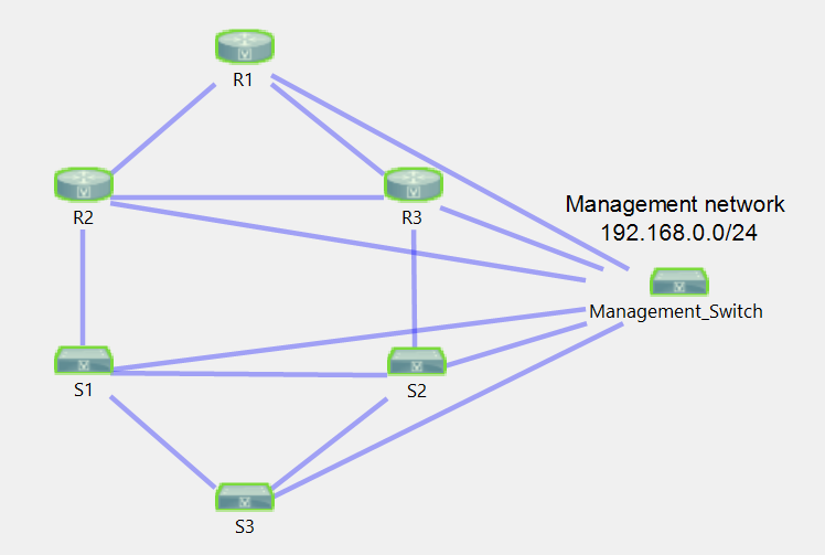
Your topology could replace the management switch with a dumb switch and have a host (such as a Raspberry Pi) connected to it, which would serve as your DHCP and TFTP server. The details do not matter – the end goal of this topology is that each device dedicates a single Ethernet interface for a management network, and the rest of the interfaces can be used for practicing configuration as you normally would in a lab. You remotely access all of the devices in your lab via Telnet, and when you finish with your lab and wish to erase your work, you simply reset each device to factory settings via a write erase command and a reload. When the device boots up, it will automatically pull your base configuration from the TFTP server. Your base configuration can contain whatever configuration best suits your needs: The goal of this article is to show you an example of what can be automated in your pod without the need for moving a console cable from device to device.
Testing
I attempted to utilize equipment that likely would be found in a CCNA or CCNP certification homelab wherever possible. However, my testing is not comprehensive; it is entirely possible that you may encounter issues with your equipment due to the multiple different combinations of Cisco hardware and software that are available.
- Management Switch
- WS-C3560X-24P-L running 15.2(3)E
- Router Clients
- CISCO1841 running 15.1(4)M12A
- C2620XM-1FE running 12.4(25d)
- C1861E-SRST-F/K9 running 15.2(4)M3
- Switch Client
- WS-C3560X-24P-L running 15.2(3)E
If you encounter issues with configuring AutoInstall on your equipment, I highly recommend updating to the latest recommended version of code, if at all possible. If that is not a feasible option, feel free to contact me with your software, hardware, and configurations! I would be more than happy to review your setup and point out any issues I can find.
Procedure
Our first step is going to be configuring our management switch to act as a DHCP server. Again, any switch can be used (whether it be a smart/managed switch or a dumb switch), so long as all devices are plugged into the switch, and the device that serves as your TFTP and DHCP server is plugged into the switch too. The following procedure assumes that you are using a Cisco device to provide TFTP and DHCP services to your networking pod.
First, let’s configure DHCP on our switch by creating a pool named LAB-DHCP, setting the scope of the pool to 192.168.0.0/24, setting our default router to 192.168.0.1, setting the TFTP server IP address option (150) of our DHCP pool to point to 192.168.0.1, and excluding the switch’s own IP (192.168.0.1) from the DHCP pool. Then, we’re going to assign 192.168.0.1/24 to our Vlan 1 interface.
1
2
3
4
5
6
7
8
9
10
11
Management#configure terminal
Management(config)#ip dhcp pool LAB-DHCP
Management(dhcp-config)#network 192.168.0.0 255.255.255.0
Management(dhcp-config)#default-router 192.168.0.1
Management(dhcp-config)#option 150 ip 192.168.0.1
Management(dhcp-config)#exit
Management(config)#ip dhcp excluded-address 192.168.0.1
Management(config)#interface Vlan1
Management(config-if)#ip address 192.168.0.1 255.255.255.0
Management(config-if)#no shut
Management(config-if)#end
At this point, if you go to another device in your topology and configure ip address dhcp on your interface facing the management switch, you should be able to obtain an IP address in the 192.168.0.0/24 range.
Before we configure our management switch to act as a TFTP server, we need to create the base configuration to be used across all our devices. The reasoning behind this is that in order to configure a device as a TFTP server in Cisco IOS, we need to choose individual files that we wish to be accessed via TFTP. As of right now, we don’t have a file that we can serve via TFTP.
To create our base configuration, we’re going to be using the TCL shell on our management switch to write commands to a file. This option is better than copying a base configuration from one of our devices, as our networking pod may have a mixture of device models, images, and types. A base configuration derived from one of those devices may cause configuration errors on other devices if interface names, image versions, or capabilities are different. When we create our configuration, we’re going to want to make sure we name it network-confg, as AutoInstall requires base configurations to be named either network-confg or cisconet.cfg.
We can access the TCL shell from privileged EXEC mode by typing the tclsh command; you should see your prompt change from Hostname# to Hostname(tcl)#, which indicates a successful transition. From this point forward, you want to tailor your base configuration to your specific needs; as I described above, my base configuration is only going to contain the necessary configuration to establish telnet connection from the management switch using a username, password, and secret of “cisco”. My commands in the TCL shell, as well as my base configuration are shown below – feel free to customize it to fit your environment.
1
2
3
4
5
6
7
8
9
10
11
12
13
14
15
16
17
Management(tcl)#puts [ open "flash:network-confg" w+ ] {
+>hostname BASE-CONFIG
+>enable secret cisco
+>ip domain name chrisjhart.com
+>username cisco password cisco
+>line vty 0 4
+> logging synchronous
+> login local
+> transport input all
+>line vty 5 15
+> logging synchronous
+> login local
+> transport input all
+>end
+>}
Management(tcl)#tclquit
Management#
We can confirm that our file wrote correctly by using the more command, which will output the contents of a file, as shown below:
1
2
3
4
5
6
7
8
9
10
11
12
13
14
15
16
Management#more flash:base-confg
hostname BASE-CONFIG
enable secret cisco
ip domain name chrisjhart.com
username cisco password cisco
line vty 0 4
 logging synchronous
 login local
 transport input all
line vty 5 15
 logging synchronous
 login local
 transport input all
end

Management#
Finally, let’s enable the TFTP server on our management switch…
1
2
Management#configure terminal
Management(config)#tftp-server flash:network-confg
…and confirm that R1 is able to copy the file from the management switch!
1
2
3
4
5
6
7
BASE-CONFIG#copy tftp://192.168.0.1/network-confg flash:test
Destination filename [test]?
Accessing tftp://192.168.0.1/network-confg...
Loading network-confg from 192.168.0.1 (via FastEthernet0/1): !
[OK - 3134 bytes]

3134 bytes copied in 0.543 secs (5772 bytes/sec)
Now let’s confirm that AutoInstall is functioning by resetting R1 to factory defaults. After we reload R1, it should automatically pull the base configuration from our management switch:
1
2
3
4
5
6
7
8
9
10
11
12
13
14
15
16
17
18
19
20
21
22
23
24
25
26
27
28
29
30
31
32
33
34
35
BASE-CONFIG#write erase
Erasing the nvram filesystem will remove all configuration files! Continue? [confirm]

[OK]
Erase of nvram: complete
*Jul 24 22:42:26.040: %SYS-7-NV_BLOCK_INIT: Initialized the geometry of nvram
BASE-CONFIG#
BASE-CONFIG#
BASE-CONFIG#reload

System configuration has been modified. Save? [yes/no]: no
Proceed with reload? [confirm]

*Jul 24 22:42:32.377: %SYS-5-RELOAD: Reload requested by console. Reload Reason: Reload Command.

<snip>

--- System Configuration Dialog ---

Would you like to enter the initial configuration dialog? [yes/no]:
Loading network-confg from 192.168.0.1 (via FastEthernet0/1): !
[OK - 1101 bytes]

%Error opening tftp://192.168.0.1/BASE-CONFIG-confg (Socket error)
%Error opening tftp://192.168.0.1/BASE-CONFIG-confg (Socket error)
%Error opening tftp://192.168.0.1/BASE-CONFIG-confg (Socket error)
%Error opening tftp://255.255.255.255/BASE-CONFIG-confg (Socket error)
%Error opening tftp://255.255.255.255/BASE-CONFIG-confg (Socket error)
%Error opening tftp://255.255.255.255/BASE-CONFIG-confg (Socket error)

Would you like to enter the initial configuration dialog? [yes/no]: no

Press RETURN to get started!
BASE-CONFIG>
BASE-CONFIG>
Success! However, we still have room for improvement; in its current shape, AutoInstall will result in all of our pod devices having the same hostname, and IP addresses will be assigned randomly. This will make remote management a bit more difficult, as we’ll need to find out which IP address each of our devices grabbed before being able to telnet into them. Let’s customize our configuration on R1 a little bit more by creating a file named R1-confg on the management switch using TCL:
1
2
3
4
5
6
7
8
9
10
11
12
13
Management(tcl)#puts [ open "flash:R1-confg" w+ ] {
+>interface FastEthernet0/1
+> ip address 192.168.0.10 255.255.255.0
+> no shutdown
+>line vty 0 15
+> login local
+> transport input all
+>username cisco password cisco
+>enable secret cisco
+>hostname R1
+>}
Management(tcl)#tclquit
Management#
Next, let’s configure our TFTP server to serve the R1-confg file:
1
Management#tftp-server flash:R1-confg
The naming scheme of this configuration file (along with all of your future, device-specific configuration files) is important. Cisco AutoInstall follows the naming scheme hostname-confg or hostname.cfg, where hostname is the hostname that you choose to give to your device. Therefore, if you want a device named “AggSw” to install a host-specific configuration automatically, you need to name that configuration file AggSw-confg on your TFTP server.
However, we must first answer an important question: how does our DHCP/TFTP server know which host-specific configuration goes with which device?
The answer is through configuring manual bindings in a DHCP pool for each individual host. In order to do this, we need to find the client identifier for each host. The easiest way to do this is to allow each device to load its base configuration from the management switch (which involves grabbing an IP address from the DHCP server), then use the show ip dhcp binding command to find the client identifier, as shown highlighted below in bold:
1
2
3
4
5
6
7
8
9
10
11
12
13
Management#show ip dhcp binding
Bindings from all pools not associated with VRF:
IP address Client-ID/ Lease expiration Type State Interface
 Hardware address/
 User name
192.168.0.10 0063.6973.636f.2d30. Infinite Manual Active Unknown
 3031.352e.3262.6433.
 2e35.6166.372d.4661.
 302f.31
192.168.0.11 0063.6973.636f.2d66. Infinite Manual Active Unknown
 3836.362e.6632.3262.
 2e32.6463.302d.566c.
 31
Once you’ve found the client-identifier for your device, you can set up a DHCP pool for that specific device. When configuring manual bindings for devices, each device requires its own specific DHCP pool. This is demonstrated below:
1
2
3
4
5
6
7
8
9
10
11
12
13
14
15
Management#show run ip dhcp pool
!
ip dhcp pool R1
 host 192.168.0.10 255.255.255.0
 client-identifier 0063.6973.636f.2d30.3031.352e.3262.6433.2e35.6166.372d.4661.302f.31
 bootfile R1-confg
 default-router 192.168.0.1
 option 150 ip 192.168.0.1
!
ip dhcp pool S1
 host 192.168.0.11 255.255.255.0
 client-identifier 0063.6973.636f.2d66.3836.362e.6632.3262.2e32.6463.302d.566c.31
 bootfile S1-confg
 default-router 192.168.0.1
 option 150 ip 192.168.0.1
Each pool identifies:
- The IP address that the host should have
- The client identifier that belongs to the host
- The configuration file that should be served to the host
- The host’s default gateway (typically the IP address of the management switch)
- The IP address of the TFTP server, so that the client knows from which TFTP server to pull the configured bootfile from.
Now that we have our configuration in place, let’s factory reset R1 and see if it pulls a configuration!
1
2
3
4
5
6
7
8
9
10
11
12
13
14
15
16
17
18
19
20
21
22
23
24
25
26
27
28
29
30
BASE-CONFIG#wr er
Erasing the nvram filesystem will remove all configuration files! Continue? [confirm]
[OK]
Erase of nvram: complete
BASE-CONFIG#reload

System configuration has been modified. Save? [yes/no]: no
Proceed with reload? [confirm]

Jan 2 12:48:59.227: %SYS-5-RELOAD: Reload requested by console. Reload Reason: Reload Command.

<snip>

Cisco 1841 (revision 5.0) with 237568K/24576K bytes of memory.
Processor board ID FTX0937Y0JV
2 FastEthernet interfaces
DRAM configuration is 64 bits wide with parity disabled.
191K bytes of NVRAM.
254464K bytes of ATA CompactFlash (Read/Write)

Loading R1-confg from 192.168.0.1 (via FastEthernet0/1): !
[OK - 191 bytes]


%Error opening tftp://255.255.255.255/network-confg (Timed out)
%Error opening tftp://255.255.255.255/cisconet.cfg (Timed out)

--- System Configuration Dialog ---

Would you like to enter the initial configuration dialog? [yes/no]:
As you can see below, we are able to ping 192.168.0.10 (which was statically assigned to Fa0/1 of R1), as well as telnet into 192.168.0.10 successfully!
1
2
3
4
5
6
7
8
9
10
11
12
13
14
15
16
17
Management#ping 192.168.0.10
 Type escape sequence to abort.
 Sending 5, 100-byte ICMP Echos to 192.168.0.10, timeout is 2 seconds:
 !!!!!
 Success rate is 100 percent (5/5), round-trip min/avg/max = 1/4/9 ms

Management#telnet 192.168.0.10
Trying 192.168.0.10 ... Open

User Access Verification

Username: cisco
Password:
R1>enable
Password:
R1#show ip int br | i up
FastEthernet0/1 192.168.0.10 YES DHCP up up
Conclusion
We are now able to create a custom configuration for each of the devices in our networking homelab, and we have confirmed that we are able to remotely configure a device, reset it to factory settings when we’re done with our lab for the day, and connect to it remotely once more after the factory-reset process is complete. This is demonstrated below, where I was able to telnet into a Cisco1841 router, factory reset and reload the device, then remotely access it once more after about 2.5 minutes:
1
2
3
4
5
6
7
8
9
10
11
12
13
14
15
16
17
18
19
20
21
22
23
24
25
26
27
28
29
30
31
32
33
34
35
36
37
38
39
40
41
42
43
44
45
46
47
Management#telnet 192.168.0.10
Trying 192.168.0.10 ... Open


User Access Verification

Username: cisco
Password:
R1>enable
Password:
R1#wr er
Erasing the nvram filesystem will remove all configuration files! Continue? [confirm]
[OK]
Erase of nvram: complete
R1#reload

System configuration has been modified. Save? [yes/no]: no
Proceed with reload? [confirm]

[Connection to 192.168.0.10 closed by foreign host]
Management#
Mar 30 15:12:29.904: %LINEPROTO-5-UPDOWN: Line protocol on Interface GigabitEthernet0/1, changed state to down
Mar 30 15:12:31.909: %LINEPROTO-5-UPDOWN: Line protocol on Interface GigabitEthernet0/1, changed state to up
Mar 30 15:13:47.692: %LINEPROTO-5-UPDOWN: Line protocol on Interface GigabitEthernet0/1, changed state to down
Mar 30 15:13:48.690: %LINK-3-UPDOWN: Interface GigabitEthernet0/1, changed state to down
Mar 30 15:13:50.813: %LINK-3-UPDOWN: Interface GigabitEthernet0/1, changed state to up
Mar 30 15:13:51.819: %LINEPROTO-5-UPDOWN: Line protocol on Interface GigabitEthernet0/1, changed state to up
Mar 30 15:13:59.772: %LINEPROTO-5-UPDOWN: Line protocol on Interface GigabitEthernet0/1, changed state to down
Mar 30 15:14:01.802: %LINEPROTO-5-UPDOWN: Line protocol on Interface GigabitEthernet0/1, changed state to up
Management#telnet 192.168.0.10
Trying 192.168.0.10 ... Open


User Access Verification

Username: cisco
Password:
R1>enable
Password:
R1#show inventory
NAME: "chassis", DESCR: "1841 chassis"
PID: CISCO1841 , VID: V01 , SN: FTX0937Y0JV

NAME: "motherboard", DESCR: "C1841 Motherboard with 2 Fast Ethernet"
PID: CISCO1841 , VID: V01 , SN: FOC09330G2K
The possibilities in the homelab are endless with automation leveraged by Cisco AutoInstall. I hope this guide was helpful!